CAS 6-NP LEM USA Inc, CAS 6-NP Datasheet - Page 12
CAS 6-NP
Manufacturer Part Number
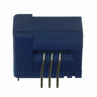
CAS 6-NP
Description
SENSOR CURRENT 6A 5V MOD
Manufacturer
LEM USA Inc
Series
CASr
Datasheet
1.CAS_25-NP.pdf
(15 pages)
Specifications of CAS 6-NP
Featured Product
CAS Series
Current - Sensing
6A
Accuracy
±0.8%
Sensitivity
104.2mV/A
Current - Supply
-
Sensor Type
Flux Gate
Voltage - Supply
4.75 V ~ 5.25 V
Output
0 ~ 5 VDC
Frequency
300kHz
Response Time
300ns
Polarization
Bidirectional
Operating Temperature
-40°C ~ 85°C
Package / Case
Module
Lead Free Status / Rohs Status
Lead free / RoHS Compliant
Other names
398-1087-5


100526/5
Ampere-turns and amperes
The transducer is sensitive to the primary current linkage
Q
Caution: As most applications will use the transducer with
only one single primary turn (N
is written in terms of primary current instead of current
linkages. However, the ampere-turns (A-t) unit is used to
emphasis that current linkages are intended and applicable.
Transducer simplified model
The static model of the transducer at temperature T
V
In which error =
V
With:
This model is valid for primary ampere-turns
-
Q
OE
OUT
P
Pmax
(also called ampere-turns).
+ V
= G
and +
OT
(T
Q
Q
Where N
depending on the connection of the primary
jumpers)
Q
Q
V
T
V
V
G
ε
ε
G
L
A
A
OUT
OE
OT
P
P
P
P
Q
) + ε
(
=N
max
Q
+ error
= N
(T
Pmax
Pmax
P
A
G
I
)
P
P
·Q
only.
I
(At)
)
P
P
I
P
P
·G + ε
the number of primary turn (1, 2 or 3
:the input ampere-turns (At)
:the maxi input ampere-turns that have
:the secondary voltage (V)
:the ambient temperature (°C)
:the electrical offset voltage (V)
:the temperature variation of V
:the sensitivity of the transducer (V/At)
:the sensitivity error
:the linearity error for
Please read above warning.
been applied to the transducer (At)
temperature T
L
LEM reserves the right to carry out modifications on its transducers, in order to improve them, without prior notice.
(Q
Pmax
P
)·Q
= 1), much of this datasheet
Performance parameters definition
Pmax
A
·G + TCG·(T
(V)
Q
Q
Pmax
P
between
A
-25)·Q
A
is:
O
at
P
·G
Sensitivity and linearity
To measure sensitivity and linearity, the primary current
(DC) is cycled from 0 to I
spaced I
The sensitivity G is defined as the slope of the linear
regression line for a cycle between ± I
The linearity error
difference between the measured points and the linear
regression line, expressed in % of I
Magnetic offset
The magnetic offset current I
current on the primary side (“memory effect” of the
transducer’s ferro-magnetic parts). It is included in the
linearity figure but can be measured individually.
It is measured using the following primary current cycle.
I
Figure 30: Current cycle used to measure magnetic and
OM
depends on the current value I
-I
0 A
I
P1
P
P1
/10 steps).
I
P
electrical offset (transducer supplied)
(DC)
t
I
OM
ε
L
=
is the maximum positive or negative
V
OUT
P
, then to -I
(
t
OM
1
)
t
1
−
2
is the consequence of a
Ip(3)
V
P1
OUT
PN
.
P
.
(
and back to 0 (equally
PN
t
2
.
)
⋅
CAS series
Gth
1
t
Ip(
3)
www.lem.com
2
t
Page 12/15
Related parts for CAS 6-NP
Image
Part Number
Description
Manufacturer
Datasheet
Request
R

Part Number:
Description:
SENSOR CURRENT 25A 5V MOD
Manufacturer:
LEM USA Inc
Datasheet:

Part Number:
Description:
SENSOR CURRENT 15A 5V MOD
Manufacturer:
LEM USA Inc
Datasheet:

Part Number:
Description:
SENSOR CURRENT 50A 5V MOD
Manufacturer:
LEM USA Inc
Datasheet:

Part Number:
Description:
SENSOR CURRENT 200A TH
Manufacturer:
LEM USA Inc
Datasheet:


Part Number:
Description:
FHS 40 PCB KIT 30/78A
Manufacturer:
LEM USA Inc
Datasheet:

Part Number:
Description:
FHS 40 PCB KIT 16/30A
Manufacturer:
LEM USA Inc
Datasheet:

Part Number:
Description:
FHS 40 PCB KIT 16/55A
Manufacturer:
LEM USA Inc
Datasheet:

Part Number:
Description:
FHS 40 PCB W/JUMPER KIT 10/10A
Manufacturer:
LEM USA Inc
Datasheet:

Part Number:
Description:
FHS 40 PCB KIT 5/16A
Manufacturer:
LEM USA Inc
Datasheet:

Part Number:
Description:
FHS 40 PCB KIT 5/11A
Manufacturer:
LEM USA Inc
Datasheet:

Part Number:
Description:
TRANSFORM CURR 100A SPLIT CORE
Manufacturer:
LEM USA Inc
Datasheet:

Part Number:
Description:
TRANSFORM CURRENT 50A SPLIT CORE
Manufacturer:
LEM USA Inc
Datasheet:

Part Number:
Description:
SENSOR CURRENT 20A 5V UNI SMD
Manufacturer:
LEM USA Inc
Datasheet:

Part Number:
Description:
SENSOR CURRENT 15A 5V UNI SMD
Manufacturer:
LEM USA Inc
Datasheet: