CKSR 6-NP LEM USA Inc, CKSR 6-NP Datasheet - Page 3
CKSR 6-NP
Manufacturer Part Number
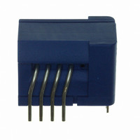
CKSR 6-NP
Description
SENSOR CURRENT 6A 5V MOD
Manufacturer
LEM USA Inc
Series
CKSRr
Datasheet
1.CKSR_25-NP.pdf
(24 pages)
Specifications of CKSR 6-NP
Current - Sensing
6A
Accuracy
±0.8%
Sensitivity
104.2mV/A
Current - Supply
-
Sensor Type
Flux Gate
Voltage - Supply
4.75 V ~ 5.25 V
Output
0 ~ 5 VDC
Frequency
300kHz
Response Time
300ns
Polarization
Bidirectional
Operating Temperature
-40°C ~ 105°C
Package / Case
Module
Lead Free Status / Rohs Status
Lead free / RoHS Compliant
Other names
398-1095-5


Compensation
Winding
CAS / CASR / CKSR Transducers Technology:
Closed Loop Fluxgate technology
Closed Loop current transducers measure current over
wide frequency ranges, including DC. They provide
contact-free coupling to the current that needs to be
measured as well as safe galvanic isolation and high
reliability. Their output signal is an accurate, high-resolution
image of the primary current with a very short delay.
In higher frequency ranges these transducers function
exactly the same way as (passive) current transformers,
where a relatively small induced voltage in the secondary
winding is capable to drive the secondary current through
the secondary winding and, most important, through
the burden resistor. A low induced voltage equals low
magnetic flux in the magnetic core, which is the cause
for the good accuracy (low flux means a small difference
between primary and secondary current linkage
For DC and in low-frequency ranges, the induced voltage
is too low to be able to drive the secondary current, and
the error of simple current transformers will increase with
decreasing frequency. In this domain, the magnetic flux
density in the core is measured by a sensing element and
a voltage is applied to the secondary circuit that in the
end keeps the flux density near zero, effectively creating a
closed control loop.
The only basic difference between the CAS / CASR / CKSR
transducer series and standard Closed Loop transducers
of LEM is that the Hall element used for feedback is
replaced by a Fluxgate detector. The driving force behind
this choice is the need for a “better” feedback, which
basically means more voltage per current linkage, a
quantity that is called “Open Loop sensitivity”. Given
an equal electronic circuit, the zero output of a current
transducer (traditionally called “offset” in analogy to
operational amplifiers) will be less influenced by changes
Fig. 1. Closed Loop Fluxgate Technology used for the CAS / CASR / CKSR current transducers
I
P
Magnetic Core
Primary conductor
Fluxgate
Interface
Fluxgate
I
1
Compensation
, too).
I
COMP1
Filter
in the electronics (e.g. offset variations of the amplifiers
used) if the Open Loop sensitivity is higher.
The complexity of a Fluxgate based current transducer
is comparable to the one of a transducer based on a Hall
effect IC (integrated circuit). Like there, some AC signal
processing and synchronous rectifying is applied. In
addition, the Fluxgate detector is needed. Fortunately,
this Fluxgate is a very simple small solenoid with a tiny
soft magnetic strip used as detector core. Because of
the complexity of the signal chain, an IC is used to stay
at a competitive cost level compared to Hall effect current
transducers. A circuit in this IC forms an oscillator together
with the Fluxgate, driving it into saturation each half cycle
at a frequency of several hundred kilohertz. The effect
that is used for the detection of a residual flux in the main
transducer core is the fact that in such a configuration a
change of the duty cycle of the driving voltage will occur
when a magnetic DC flux is present in the fluxgate core.
The signal processing stages in the IC comprise a duty
cycle demodulation, frequency response compensation,
an integrator and a bridge amplifier that provides the
secondary current. This output architecture can provide
a higher (doubled) voltage to the secondary circuit when
compared to a single output stage with the other side of the
circuit connected to a reference potential at typically 2.5 V.
In this configuration, the burden (or measurement) resistor
is floating, so in order to obtain an output signal referenced
to a fixed voltage, a difference amplifier is used which is
also part of the IC.
1
Current linkage is the technical term for current multiplied by turns count
Driver
R
S
I
COMP2
Amp
Diff
GND
Int. ref
+5V
V
OUT
V
REF
3
Related parts for CKSR 6-NP
Image
Part Number
Description
Manufacturer
Datasheet
Request
R

Part Number:
Description:
SENSOR CURRENT 25A 5V MOD
Manufacturer:
LEM USA Inc
Datasheet:

Part Number:
Description:
SENSOR CURRENT 15A 5V MOD
Manufacturer:
LEM USA Inc
Datasheet:

Part Number:
Description:
SENSOR CURRENT 50A 5V MOD
Manufacturer:
LEM USA Inc
Datasheet:

Part Number:
Description:
SENSOR CURRENT 200A TH
Manufacturer:
LEM USA Inc
Datasheet:


Part Number:
Description:
FHS 40 PCB KIT 30/78A
Manufacturer:
LEM USA Inc
Datasheet:

Part Number:
Description:
FHS 40 PCB KIT 16/30A
Manufacturer:
LEM USA Inc
Datasheet:

Part Number:
Description:
FHS 40 PCB KIT 16/55A
Manufacturer:
LEM USA Inc
Datasheet:

Part Number:
Description:
FHS 40 PCB W/JUMPER KIT 10/10A
Manufacturer:
LEM USA Inc
Datasheet:

Part Number:
Description:
FHS 40 PCB KIT 5/16A
Manufacturer:
LEM USA Inc
Datasheet:

Part Number:
Description:
FHS 40 PCB KIT 5/11A
Manufacturer:
LEM USA Inc
Datasheet:

Part Number:
Description:
TRANSFORM CURR 100A SPLIT CORE
Manufacturer:
LEM USA Inc
Datasheet:

Part Number:
Description:
TRANSFORM CURRENT 50A SPLIT CORE
Manufacturer:
LEM USA Inc
Datasheet:

Part Number:
Description:
SENSOR CURRENT 20A 5V UNI SMD
Manufacturer:
LEM USA Inc
Datasheet:

Part Number:
Description:
SENSOR CURRENT 15A 5V UNI SMD
Manufacturer:
LEM USA Inc
Datasheet: