DHR 100 C10 LEM USA Inc, DHR 100 C10 Datasheet
DHR 100 C10
Specifications of DHR 100 C10


Related parts for DHR 100 C10


DHR 100 C10 Summary of contents
Page 1
... LEM reserves the right to carry out modifications on its transducers, in order to improve them, without prior notice. Output voltage Type (Analog (VDC) OUT 0-10 DHR 100 C10 0-10 DHR 200 C10 0-10 DHR 300 C10 0-10 DHR 400 C10 0-10 DHR 500 C10 ...
Page 2
... Current Transducer DHR-C10 Isolation characteristics V Rated isolation voltage rms 3) b according to the standard IEC 61010-1 and with the following conditions: - Reinforced isolation - Over voltage category CAT III - Pollution degree PD2 - Heterogeneous field V Rms voltage for AC isolation test d V Impulse withstand voltage , 1 ...
Page 3
... Current Transducer DHR-C10 Safety and warning notes In order to guarantee safe operation of the transducer and to be able to make proper use of all features and functions, please read these instructions thoroughly! Safe operation can only be guaranteed if the transducer is used for the purpose it has been designed for and within the limits of the technical specifications ...
Page 4
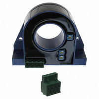
Dimensions DHR-C5 (in mm 0.0394 inch) Dimensions DHR-C10 (in mm 0.0394 inch) Dimensions DHR-C5 (in mm 0.0394 inch DHR DHR Output Connector 1(Vcc) 2(NC) 3(Vout) 4(GND) Output Connector 24 ...