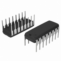
MC14051BCPG ON Semiconductor, MC14051BCPG Datasheet - Page 6

MC14051BCPG
Manufacturer Part Number
MC14051BCPG
Description
IC MUX/DEMUX 8X1 16DIP
Manufacturer
ON Semiconductor
Series
4000Br
Type
Analog Multiplexerr
Datasheet
1.MC14051BDTR2G.pdf
(12 pages)
Specifications of MC14051BCPG
Function
Multiplexer/Demultiplexer
Circuit
1 x 8:1
On-state Resistance
280 Ohm
Voltage Supply Source
Dual Supply
Voltage - Supply, Single/dual (±)
±3 V ~ 18 V
Current - Supply
0.36µA
Operating Temperature
-55°C ~ 125°C
Mounting Type
Through Hole
Package / Case
16-DIP (0.300", 7.62mm)
On Resistance (max)
1050 Ohms
Propagation Delay Time
90 ns
On Time (max)
700 ns
Off Time (max)
700 ns
Supply Voltage (max)
18 V
Supply Voltage (min)
3 V
Maximum Power Dissipation
500 mW
Maximum Operating Temperature
+ 125 C
Minimum Operating Temperature
- 55 C
Mounting Style
Through Hole
Number Of Switches
Single
Multiplexer Configuration
Single 8:1
Number Of Inputs
8
Number Of Outputs
1
Number Of Channels
1
Analog Switch On Resistance
1050@5VOhm
Analog Switch Turn On Time
700ns
Analog Switch Turn Off Time
700ns
Package Type
PDIP
Power Supply Requirement
Single
Single Supply Voltage (min)
3V
Single Supply Voltage (typ)
5/9/12/15V
Single Supply Voltage (max)
18V
Dual Supply Voltage (min)
Not RequiredV
Dual Supply Voltage (typ)
Not RequiredV
Dual Supply Voltage (max)
Not RequiredV
Power Dissipation
500mW
Mounting
Through Hole
Pin Count
16
Operating Temp Range
-55C to 125C
Operating Temperature Classification
Military
Lead Free Status / RoHS Status
Lead free / RoHS Compliant
Other names
MC14051BCPGOS
Available stocks
Company
Part Number
Manufacturer
Quantity
Price
Company:
Part Number:
MC14051BCPG
Manufacturer:
ON
Quantity:
1 000
Part Number:
MC14051BCPG
Manufacturer:
ON/安森美
Quantity:
20 000
NOTE: See also Figures 7 and 8 in the MC14016B data sheet.
V
A, B, and C inputs used to turn ON
or OFF the switch under test.
Figure 7. Bandwidth and Off−Channel
DD
V
2
- V
SS
Figure 9. Crosstalk, Control Input to
EE
Figure 5. DV Across Switch
CONTROL
Feedthrough Attenuation
SECTION
OF IC
SOURCE
A
B
C
INH
A
B
C
INH
Common O/I
V
in
V
ON SWITCH
R1
R
L
R
LOAD
L
C
L
= 50 pF
C
V
L
out
= 50 pF
V
out
http://onsemi.com
TEST CIRCUITS
6
GENERATOR
V
PULSE
DD
(Adjacent Channels Used For Setup)
CONTROL
- V
2
SECTION
Figure 6. Propagation Delay Times,
OF IC
Figure 10. Off Channel Leakage
EE
Figure 8. Channel Separation
Control and Inhibit to Output
A
B
C
INH
A
B
C
INH
COMMON
ON
OFF
V
OFF CHANNEL UNDER TEST
V
DD
OTHER
CHANNEL(S)
in
V
EE
R
L
R
V
L
EE
R
L
V
DD
V
V
V
V
V
V
C
DD
EE
EE
DD
EE
DD
L
= 50 pF
C
V
out
L
V
out


