DM320011 Microchip Technology, DM320011 Datasheet - Page 14
DM320011
Manufacturer Part Number
DM320011
Description
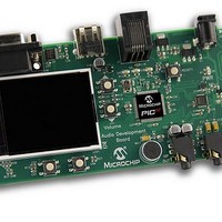
PIC32MX Audio Development Board Other
Manufacturer
Microchip Technology
Series
PIC® 32r
Datasheet
1.DM320011.pdf
(24 pages)
Specifications of DM320011
Description/function
Audio CODECs
Operating Supply Voltage
9 V
Product
Audio Development Tools
Silicon Core Number
PIC32MX
Core Architecture
PIC
Core Sub-architecture
PIC32
Features
On-board PIC32MX795F512 With 80MIPS Of Performance, 512KB Flash And 128KB Of RAM, Microphone
Main Purpose
Audio, Audio Processing
Embedded
Yes, MCU, 32-Bit
Utilized Ic / Part
PIC32MX795F512
Primary Attributes
USB Type A Interface, MFi Dock Edge Connector
Secondary Attributes
24-Bit Wolfson CODEC
Lead Free Status / Rohs Status
Details
For Use With/related Products
PIC32MX795F512


2.3
2.4
2.5
2.6
DS70662A-page 14
AUDIO CODEC, MICROPHONE AND AUDIO CONNECTIONS
PICtail™ PLUS CONNECTOR
TFT DISPLAY
USB CONNECTIVITY
The audio codec (U1) is a Wolfson WM8960. The codec is of hi-fi quality with up to
24-bit resolution. The sampling rates supported are between 8 kHz to 48 kHz and
includes an on-chip flexible PLL. The codec has a built-in headphone driver and a ste-
reo Class D speaker driver. In addition, it has low-power consumption and offers a
small foot print. On 32-bit microcontroller, the codec data interface is handled through
the SPI module in Framed SPI mode. On 16-bit microcontroller, the codec data inter-
face is handled through the DCI module. The control registers of the codec are config-
ured over the I
oscillator.
The condenser microphone (MIC1) is available on the board for capturing audio. The
microphone bias voltage is provided directly by the codec and is connected via Line
Input 1 of the codec. The microphone bias voltage level and sensitivity are controlled
via the codec registers. The microphone signal is presented as a mono signal to the
application.
The line-in jack (Line IN) is available to interface to audio signal sources (such as CD
players and musical instruments) that use line level ouputs.The line input signal is a
stereo signal and is connected to Left Input 2 and Right Input 2 of the codec.
The Headphone jack (HP OUT) is a 3.5 mm stereo socket that connects to the codec
headphone amplifier, with the headphone signal output as a true stereo signal. Any
commercially available headphone can be connected to the headphone jack. The
headphone volume and the headphone input signal are configurable via the codec
registers. The codec outputs a maximum of 20 mW into a 32 Ohm headphone.
The expansion connector (J2) on the Audio Development Board can be used to enable
Made for iPod (MFi) features for an iPod
connector is not compatible with any other PICtail Plus Daughter boards.
The Audio Development Board has a 2 inch TFT display (LCD1) with a resolution of
220x176 for a maximum of 262K colors. The display is controlled by a chip-on-glass
OTM2201A display controller. The display controller requires 8-bit parallel interface.
The Parallel Master Port (PMP) on the MCU is used to interface to the display
controller.
The Audio Development Board features USB Host support (J7). This connector allows
applications to interface to USB devices such as a USB Thumb Drive, USB mouse, and
so on. The USB module on the MCU provides the required USB Host functionality. A
5V switch controlled by the MCU controls the power supply to the attached USB device.
Note:
The maximum line input signal level should not exceed 0.5Vrms on
differential and 1Vrms on single-ended input.
2
C interface. The codec external clock is provided by a 12 MHz crystal
®
PICtail Plus board. The PICtail Plus
© 2011 Microchip Technology Inc.
Related parts for DM320011
Image
Part Number
Description
Manufacturer
Datasheet
Request
R

Part Number:
Description:
Manufacturer:
Microchip Technology Inc.
Datasheet:
Part Number:
Description:
Manufacturer:
Microchip Technology Inc.
Datasheet:
Part Number:
Description:
Manufacturer:
Microchip Technology Inc.
Datasheet:
Part Number:
Description:
Manufacturer:
Microchip Technology Inc.
Datasheet:
Part Number:
Description:
Manufacturer:
Microchip Technology Inc.
Datasheet:
Part Number:
Description:
Manufacturer:
Microchip Technology Inc.
Datasheet:
Part Number:
Description:
Manufacturer:
Microchip Technology Inc.
Datasheet:
Part Number:
Description:
Manufacturer:
Microchip Technology Inc.
Datasheet: