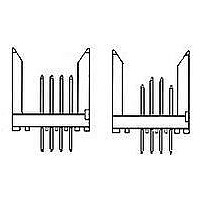
223615-1 TE Connectivity, 223615-1 Datasheet - Page 5

223615-1
Manufacturer Part Number
223615-1
Description
High Speed / Modular Connectors 144P 2MM HDR ASSY
Manufacturer
TE Connectivity
Series
223615r
Specifications of 223615-1
Number Of Rows
1
Number Of Positions / Contacts
144
Pitch
2 mm
Mounting Style
Through Hole
Termination Style
Solder Pin
Housing Material
Liquid Crystal Polymer
Contact Material
Phosphor Bronze
Contact Plating
Gold
Product Type
Connector
Connector Type
Header
Pcb Mounting Orientation
Vertical
Post Type
Press-Fit
Module Type
Signal
Voltage Rating (vac)
30
Number Of Signal Positions
144
Sequencing
Yes
Sequencing Configuration Row A
Mating Post Length 6.5mm, Termination Post Length 4.25mm, Mating Post Length 8mm, Termination Post Length 4.25mm
Sequencing Configuration Row B
Mating Post Length 6.5mm, Termination Post Length 4.25mm, Mating Post Length 8mm, Termination Post Length 4.25mm
Sequencing Configuration Row C
Mating Post Length 6.5mm, Termination Post Length 4.25mm, Mating Post Length 8mm, Termination Post Length 4.25mm
Sequencing Configuration Row D
Mating Post Length 6.5mm, Termination Post Length 4.25mm, Mating Post Length 8mm, Termination Post Length 4.25mm
Post Plating
Tin Lead over Nickel
Centerline, Matrix (mm [in])
2.00 x 2.00 [.079 x .079]
Contact Type
Pin
Contact Base Material
Phosphor Bronze
Contact Plating, Mating Area, Material
Gold (30)
Connector Style
Plug
Rohs/elv Compliance
RoHS compliant, ELV compliant
Lead Free Solder Processes
Not relevant for lead free process
Rohs/elv Compliance History
Always was RoHS compliant
Applies To
Printed Circuit Board
Application
Free-Board
Lead Free Status / Rohs Status
Details
3.6.
4.
4.1.
Rev C
Product Qualification and Requalification Test Sequence
QUALITY ASSURANCE PROVISIONS
Qualification Testing
A.
NOTE
Sample Selection
1.
Examination of product
Termination resistance
Insulation resistance
Dielectric withstanding voltage
Temperature rise vs current
Vibration
Physical shock
Durability
Mating force
Unmating force
Thermal shock
Humidity-temperature cycling
Temperature life
Mixed flowing gas
(a) See paragraph 4.1.A.
(b) Numbers indicate sequence in which tests are performed.
(c)
(d) Precondition samples with 10 cycles durability.
(e) Precondition samples with 25 cycles durability.
(f)
(g) Signal connectors only.
(h) 70° C for 1000 hours, see Figure 2.
(I)
(m) Precondition samples with 5 cycles of durability (right angle headers only).
Signal connectors.
Signal connector housings and contacts shall be prepared in accordance with applicable
Instruction Sheets and shall be selected at random from current production. All test groups
shall consist of 5 connectors each of the largest available size. All tests requiring individual
contact measurements shall be conducted on 30 contacts randomly selected over the 5
connectors. Test groups 1, 2 and 3 shall be mounted on printed circuit boards designed to
accommodate vibration and physical shock fixturing providing a series circuit for all contacts
with access to measure termination resistance.
Test or Examination
Discontinuities shall not be measured. Energize at 18° C level for 100% loadings per Test
Specification 109-151.
Precondition samples with 250 cycles durability.
105° C for 500 hours, see Figure 2.
1,9
3,7
1
5
6
4
2
8
Figure 3
3(f)(h)
1,5
2,4
2
Test Sequence (b)
Test Group (a)
3(e)(m)
1,5
2,4
3
1,8
2,6
3,7
4
4
5
5(g)
4(d)
6(c)
5(I)
1,9
2,7
3,8
108-1441
5 of 8


