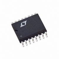
LTC201ACS Linear Technology, LTC201ACS Datasheet

LTC201ACS
Specifications of LTC201ACS
Available stocks
Related parts for LTC201ACS
LTC201ACS Summary of contents
Page 1
... Max analog multiplexers, sample-and-hold circuits, precision charge switching and remote switching. These three devices are differentiated by the type of switch action, as shown in the logic table. , LTC and LT are registered trademarks of Linear Technology Corporation. Micropower 100Hz to 1MHz V-to-F Converter 1.5M 1N4148 12k 1µ ...
Page 2
... Consult LTC Marketing for parts specified with wider operating temperature ranges. = 25° LTC201AM/LTC202M/ MIN T MIN 25°C T MAX = 1mA DS = ±14V TOP VIEW ORDER PART NUMBER 1 16 IN2BP LTC201ACN LTC201ACS + LTC202CN LTC202CS LTC203CN LTC203CS 8 9 IN3 N PACKAGE 16-LEAD PDIP = 110 C, - 120C PACKAGE 16-LEAD PLASTIC SO = 110 C, ...
Page 3
U DIGITAL ELECTRICAL CHARACTERISTICS apply over full operating temperature range, otherwise specifications are at T PARAMETER CONDITIONS Off Output Leakage I (0FF ±14V Switch Off On Channel Leakage l (ON ...
Page 4
LTC201A/LTC202/LTC203 U DIGITAL ELECTRICAL CHARACTERISTICS apply over full operating temperature range, otherwise specifications are at T PARAMETER CONDITIONS Analog Signal Range ±1.5V, + 0.25mA ∆ ...
Page 5
W U TYPICAL PERFOR A CE CHARACTERISTICS Over Supply Voltage ° 5V SUPPLY 250 I = 1mA D 200 150 ± 5V 100 ± 10V ± 15V ...
Page 6
LTC201A/LTC202/LTC203 U U APPLICATIO S I FOR ATIO Switching Time Test Circuit Switch output waveform shown for V logic input waveform as shown. Note that V – as per switching time test circuit. V LOGIC “1” ...
Page 7
U U APPLICATIO S I FOR ATIO OIRR-Off Isolation Test Circuit 15V C SIGNAL V V GENERATOR P 100kHz CHAN A ANALYZER V D CHAN B GND R L 1kΩ 0.001µF//0.1µF ...
Page 8
LTC201A/LTC202/LTC203 U U APPLICATIO S I FOR ATIO Micropower, ±4.5V to ±15V, Voltage Inverter Using the LTC203 4.5V 15µA 15V 125µA LTC201A/ IN1 LTC202/ LTC203 NC SAMPLE IN2 HOLD IN3 HOLD NO SAMPLE IN4 V S1 ...
Page 9
U U APPLICATIO S I FOR ATIO INPUT 15V + LT1028 – – 15V NOISE: 40nV 0.1Hz TO 10Hz P 1µV OS DRIFT: 0.05µV/°C R2 GAIN ...
Page 10
LTC201A/LTC202/LTC203 U U APPLICATIO S I FOR ATIO 1N4148 1N4148 1N4148 1N4148 15V 36.5kΩ 10kΩ 1%** INPUT – ± 10V LT1056 + – 15V * POLYSTYRENE 50ppm/°C DRIFT 0.04% LINEARITY ** TRW/IRC MTR/5/+ 120 Bipolar (AC) Input ...
Page 11
U U APPLICATIO S I FOR ATIO Micropower Thermocouple Temperature to Frequency Converter TYPE K THERMOCOUPLE 6V “A” 100k + V K – + LT1025 R – GND 6.81k ** C3 0.47 F 100 C 1.5k TRIM 3 S1 NOTES: ...
Page 12
LTC201A/LTC202/LTC203 U U APPLICATIO S I FOR ATIO 4.5V TO 20V Precision Current Sensing in Supply Rails SHUNT CAN BE IN POSITIVE OR NEGATIVE SUPPLY ...
Page 13
PACKAGE DESCRIPTIO CORNER LEADS OPTION (4 PLCS) .023 – .045 (0.584 – 1.143) HALF LEAD OPTION .045 – .065 (1.143 – 1.65) FULL LEAD OPTION .300 BSC (7.62 BSC) .008 – .018 0° – 15° (0.203 – 0.457) NOTE: LEAD ...
Page 14
LTC201A/LTC202/LTC203 PACKAGE DESCRIPTIO .300 – .325 (7.620 – 8.255) .008 – .015 (0.203 – 0.381) +.035 .325 –.015 ( ) +0.889 8.255 –0.381 NOTE: INCHES 1. DIMENSIONS ARE MILLIMETERS *THESE DIMENSIONS DO NOT INCLUDE MOLD FLASH OR PROTRUSIONS. MOLD FLASH ...
Page 15
... MOLD FLASH OR PROTRUSIONS SHALL NOT EXCEED .006" (0.15mm) Information furnished by Linear Technology Corporation is believed to be accurate and reliable. However, no responsibility is assumed for its use. Linear Technology Corporation makes no represen- tation that the interconnection of its circuits as described herein will not infringe on existing patent rights. ...
Page 16
... McCarthy Blvd., Milpitas, CA 95035-7417 (408) 432-1900 FAX: (408) 434-0507 www.linear.com COMMENTS Parallel Controlled with Data Latches = 35Ω Single-Ended/70Ω Differential ±15V 45Ω, Low Charge Injection ON 100MHz Pixel Switching, 1100V/µs Slew Rate LW/TP 1102 1K REV B • PRINTED IN USA LINEAR TECHNOLOGY CORPORATION 1991 201a23fb ...


