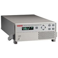
2306-VS KEITHLEY, 2306-VS Datasheet - Page 6

2306-VS
Manufacturer Part Number
2306-VS
Description
58T8427
Manufacturer
KEITHLEY
Datasheet
1.2306-VS.pdf
(8 pages)
Specifications of 2306-VS
No. Of Outputs
2
Output Voltage
15V
Output Voltage 2
15V
Output Current
5A
Output Current 2
5A
Load Regulation
0.01%
Length
411mm
Width
213mm
Height
89mm
Weight
3.9kg
Power Supply Output Type
Variable
Input Voltage
100VAC To 120VAC / 220VAC To 240VAC
Power Rating
50W
2306-VS
Voltage Stepping Only
TEST CONDITIONS:
1. Trigger external is enabled on both channels.
2. Only a single channel is externally triggered during the sequence while remaining channel
3. Times based on 0 programmable user delay.
Auto Measurement Only
TEST CONDITIONS:
1. Trigger external is enabled on both channels.
2. Only a single channel is externally triggered during the sequence while remaining channel
3. Times based on 0 programmable user delay.
4. Measurement time = 167µs (0.01 PLC).
5. Steps points = 4.
Measurement
Output #1 (Battery)
A = 70 µs typical
B = 330 µs typical
C = Programmable user delay (0–5 seconds)
D = 400 µs typical with C as 0
Output #1 (Battery)
A = 43 µs typical
B = Programmable user delay (0–5 seconds)
C = Measurement time
D = 410 µs typical (steps 1, 2, and 3)
E = 620 µs typical for steps 1, 2, and 3
Trigger Out
stays idle.
stays idle.
Trigger In
Trigger Out
Channel
Channel
with B as 0
8ms typical for step 4 with B as 0
Voltage
1.888.KEITHLEY
Output
Trigger In
Channel
Channel
w w w.keithley.com
Time
A
A
B
C
(U.S. only)
D
Output #2 (Charger)
A = 55 µs typical
B = 545 µs typical
C = Programmable user delay (0–5 seconds)
D = 600 µs typical with C as 0
Output #2 (Charger)
A = 43 µs typical
B = Programmable user delay (0–5 seconds)
C = Measurement time
D = 650 µs typical (steps 1, 2, and 3)
E = 860 µs typical for steps 1, 2, and 3
E
B
with B as 0
8ms typical for step 4 with B as 0
C
D
Dual-Channel Battery/Charger
Simulator with External Triggering
A
Voltage Stepping With Auto Measurement
TEST CONDITIONS:
1. Trigger external is enabled on both channels.
2. Only a single channel is externally triggered during the sequence while remaining channel
3. Times based on 0 programmable user delay.
4. Measurement time = 167µs (0.01 PLC).
5. Steps points = 4.
Voltage Stepping Both Channels With Channel 1
TEST CONDITIONS:
1. Only a single channel is externally triggered during the sequence while remaining channel
2. Times based on 0 programmable user delay.
Output Voltage
Output Voltage
Measurement
G R E A T E R
Output #1 (Battery)
A = 70 µs typical
B = 43 µs typical
C = Programmable user delay (0–5 seconds)
D = Measurement time
E = 475 µs typical (steps 1, 2, and 3)
F = 755 µs typical steps 1, 2, and 3 with C as 0
Output #1 (Battery)/Output #2 (Charger)
A = 70 µs typical
B = 55 µs typical
C = 775 µs typical
D = Programmable user delay (0–5 seconds)
E = 900 µs typical with D as 0
stays idle.
stays idle.
Trigger Out
Trigger Out
8 ms typical step 4 with C as 0
Channel 1
Channel 1
Channel 2
Trigger In
Channel 1
Channel
Channel
Trigger In
Voltage
Output
Time
M E A S U R E
A
A
B
O F
B
C
C O N F I D E N C E
Output #2 (Charger)
A = 55 µs typical within
B = 43 µs typical within
C = Programmable user delay (0–5 seconds)
D = Measurement time
E = 955 µs typical (steps 1, 2, and 3)
F = 1.22 ms typical steps 1, 2, and 3 with C as 0
E
F
D
8 ms typical step 4 with C as 0
C
D
E


