3402-F KEITHLEY, 3402-F Datasheet - Page 3
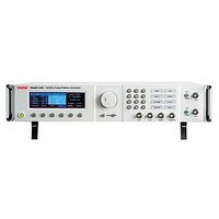
3402-F
Manufacturer Part Number
3402-F
Description
58T8436
Manufacturer
KEITHLEY
Datasheet
1.3401-F.pdf
(4 pages)
Specifications of 3402-F
Supply Voltage Range
100V To 240V
External Height
87mm
External Width
439mm
External Depth
393mm
Signal Generator Type
Burst / External Width / Pattern / Pulse


Series 3400
• Rear output option: Moves the BNC, Trigger,
• Reference oscillator input and output:
• Ports for gPIB and uSB interfaces: Allow
• Trigger Modes
• Pulse Period Source and Burst/Pattern
• Amplitude Settings: High/Low level or
• Timing: Delay and duration are fully adjust-
• Transition Time: Leading and trailing edges
• Pattern: PRBS (2
and Strobe outputs and Clock and External
inputs from the instrument’s front panel
to the rear for greater convenience in rack-
mounted environments.
Simplify coordinating multiple Series 3400
Signal generators with an external 10MHz
signal for PLL reference.
controlling the instrument via an external
computer, rather than the front panel con-
trols.
– Continuous: Trigger circuitry is always
– Triggered: Trigger arming is edge sensitive,
– Gated: Trigger arming circuitry is level sen-
Period Source
– PLL oscillator
– VCO (triggerable oscillator)
– CLK IN
Amplitude/Offset are adjustable. Source impe-
dance selectable, 50W or 1kW. Amplitudes
double for 1kW. Channels have independent
settings. Amplitudes may be set in either volt-
age or current units.
able. Can also be programmed as duty cycle.
Period is adjustable and can also be set as fre-
quency. In NRZ pattern mode, crossing point
is available instead of duration/duty cycle.
Delay and duration are independently adjust-
able for each channel. Period is a common
parameter.
can be independently adjusted for each
channel.
programmable, or preset patterns can be
specified. NRZ or RZ formats. User and preset
patterns are two bits to 16 kbits in length.
1.888.KEITHLEY
armed.
requires a selected edge prior to allowing
trigger event.
sitive, always armed when selected level is
present.
w w w.keithley.com
n
-1 with n = 5–14), user
(U.S. only)
Specifications
BASIC MODES OF OPERATION
The 340x Signal Generator may be set in one of four available
modes: Pulse, Pattern, Burst, and External Width.
PULSE/LEVEL PARAMETERS
PuLSe AMPLITuDe
LeVeL WInDoW
AMPLITuDe ACCuRACY
oFFSeT ACCuRACY
ouTPuT ReSoLuTIon: 10mV, 50 into 50
oVeRSHooT/PRe-SHooT/RIngIng
SouRCe IMPeDAnCe
SHoRT CIRCuIT CuRRenT
NOTES
1. Amplitude may be set in either voltage or current units.
2. Level may be set in either voltage or current units.
3. 50 into 50.
4. 50 into 50.
5. ±1% at 10V p-p typical. ±2% at 5V p-p typical.
6. ±1% typical.
7. ±800mA in Channel Add Mode.
BURST MODE PARAMETERS
nuMBeR oF PuLSeS: 2–65,536.
PATTERN MODE PARAMETERS
PATTeRn:
DATA FoRMATS: NRZ, RZ.
Signal Generators
Pulse Mode delivers a single pulse per trigger event to the
outputs. The pulse is programmable in delay and duration.
Burst Mode results in a “burst” of n pulses per trigger event,
with pulses configured similarly to single pulses in Pulse
mode.
Pattern Mode delivers a programmable pattern per trigger
event to the outputs. The pattern is programmable or may
be selected from a library of pre-configured patterns. The
pattern may be presented in either NRZ or RZ formats. In
NRZ mode, the pattern crossing point is programmable. In
RZ mode, the duration (duty cycle) of the pattern pulse is
programmable.
external Width Mode makes the pulse level follow the edges
of the Ext In input. A rising edge causes the output to go
high, while a falling edge causes the output to go low.
Data Pattern Length: 2–16,384 bits. Pattern for each chan-
PRBS: 2
nel is independent, must be same length.
n–1
with n = 5–14.
2
:
1
4
: 100mV to +10V, 50 into 50.
: ±100mV
200mV to +20V, 1k into 50.
–10V to +10V, 50 into 50.
–20V to +20V, 1k into 50.
6
: 50 or 1k, selectable.
20mV, 1k into 50
3
: ±(0.5% amplitude + 30mV).
7
: ±400mA.
A
G R E A T E R
5
: ±5% ±20mV.
M E A S U R E
TIMING AND TRIGGER PARAMETERS
FRequenCY RAnge
PeRIoD: 6.06ns to 1000s.
PuLSe WIDTH
WIDTH ACCuRACY: ± 0.5% ± 250ps typical with self-cal.
DeLAY
DeLAY ACCuRACY: ±0.5% ± 0.5ns typical with self-cal.
DeLAY AnD WIDTH ReSoLuTIon: 3.5 digits, 20ps best case.
DeLAY AnD WIDTH JITTeR, RMS: 0.01% + 15ps.
FIxeD DeLAY
NOTES
1. Range reduced for 1k source impedance.
2. At 50% level. Specified at fastest rise/fall and for amplitudes <5V p-p.
3. Delay is measured from Trigger Out to Pulse Out, and is the sum of the
4. Nominal.
RISE/FALL PARAMETERS
RISe/FALL TIMe: <2.5ns to 200ms, adjustable.
MInIMuM RISe/FALL TIMe
RISe/FALL TIMe ACCuRACY: ±10% ±200ps.
RISe/FALL RAngeS: 2ns–20ns, 10ns–200ns, 100ns–2µs,
NOTES
1. 10% to 90%, 50 source and load, at 25°C. Higher for 1k source impe-
CLK IN AND EXT IN PARAMETERS
InPuT IMPeDAnCe: 50 or 10k.
THReSHoLD: –3V to +3V.
MAxIMuM InPuT VoLTAge: ±6V.
CouPLIng: DC.
TRIG OUT AND STROBE OUT
PARAMETERS
ouTPuT IMPeDAnCe: 50.
LeVeLS: TTL (0V/2.4V).
MAxIMuM exTeRnAL VoLTAge: –2V to 5V.
CouPLIng: DC.
REF OSC IN AND REF OSC OUT
PARAMETERS
IMPeDAnCe: 50, AC coupled.
ReF oSC In SIgnAL: 10MHz, 0dBm typical, 20dBm max.
ouTPuT AMPLITuDe: 10MHz, 1V p-p typical.
Period Accuracy: PLL: ±0.01%. VCO: ±0.5% typical with self-
Period Resolution: PLL: 4 digits, 1ps best case.
Period Jitter, RMS: VCO: 0.015% + 20ps. PLL: 0.001% + 15ps.
2.3ns typical at 5V p-p. 2.1ns typical at 2V p-p.
1µs–20µs, 10µs–200µs, 100µs–2ms, 1ms–20ms, 10ms–
200ms.
user defined Delay plus the Fixed Delay.
dance, rising and falling edges independent within selected ranges.
O F
cal, ±3% without self-calibration.
3
: 0 to (period – 3.02 ns).
C O N F I D E N C E
4
2
: 22ns.
: 3.02ns to (period – 3.02ns).
±3% ± 0.5ns without self-cal.
±3% ± 250ps without self-cal.
1
: 1mHz to 165MHz.
VCO: 3.5 d igits, 10ps best case.
1
: 2.5ns maximum at 10V p-p.