DM330012 Microchip Technology, DM330012 Datasheet
DM330012
Specifications of DM330012
Available stocks


Related parts for DM330012

DM330012 Summary of contents
Page 1
... USB Starter Kit and © 2010-2011 Microchip Technology Inc. PIC24E USB Starter Kit User’s Guide DS51936B ...
Page 2
... PICtail, REAL ICE, rfLAB, Select Mode, Total Endurance, TSHARC, UniWinDriver, WiperLock and ZENA are trademarks of Microchip Technology Incorporated in the U.S.A. and other countries. SQTP is a service mark of Microchip Technology Incorporated in the U.S.A. All other trademarks mentioned herein are property of their respective companies. ...
Page 3
... High-Level Block Diagram ............................................................................ 15 2.2 Features ....................................................................................................... 16 Appendix A. Board Layout and Schematics A.1 Starter Kit Board Layout ............................................................................... 19 A.2 Application Hardware Schematics ............................................................... 21 A.3 Starter Kit Debugger Hardware Schematics ................................................ 26 © 2010-2011 Microchip Technology Inc. dsPIC33E/PIC24E USB STARTER KIT USER’S GUIDE Table of Contents DS51936B-page 3 ...
Page 4
... NOTES: DS51936B-page 4 © 2010-2011 Microchip Technology Inc. ...
Page 5
... Chapter 2. “Hardware” each starter kit. • Appendix A. “Board Layout and Schematics” diagram, board layouts, and detailed schematics of each starter kit. © 2010-2011 Microchip Technology Inc. dsPIC33E/PIC24E USB STARTER KIT USER’S GUIDE Preface NOTICE TO CUSTOMERS – This chapter provides a brief overview of each – ...
Page 6
... Optional arguments mcc18 [options] file [options] Choice of mutually exclusive errorlevel {0|1} arguments selection Replaces repeated text var_name [, var_name...] Represents code supplied by void main (void) user { ... } © 2010-2011 Microchip Technology Inc. Examples ® IDE User’s Guide ...
Page 7
... Universal Serial Bus Specification and Associated Documents The Universal Serial Bus is defined by the USB 2.0 Specification and its associated supplements and class-specific documents. These documents are available from the USB Implementers Forum. See their website at: © 2010-2011 Microchip Technology Inc. ® DSCs User’s Guide http://www.usb.org. ...
Page 8
... MPLAB IDE, MPLAB SIM simulator, MPLAB IDE Project Manager and general editing and debugging features. • Programmers – The latest information on Microchip programmers. These include the MPLAB PM3 device programmer and the PICkit™ 3 development programmers. DS51936B-page 8 ® © 2010-2011 Microchip Technology Inc. ...
Page 9
... Replaced OTG with DEVICE in the Power Distribution/Switching schematic (Figure A-4) and added “Do not populate” in the USB Connections schematic (Figure A-8) in © 2010-2011 Microchip Technology Inc. 1.2.1 “Top Assembly” and 1.2.2 “Bottom Assembly” Figure 2-1 2.2.2 “Power Supply” ...
Page 10
... NOTES: DS51936B-page 10 © 2010-2011 Microchip Technology Inc. ...
Page 11
... Chapter 1. Introduction Thank you for purchasing a Microchip Technology dsPIC33E USB Starter Kit or PIC24E USB Starter Kit. Depending on the starter kit purchased, the board included provides a low-cost, modular development system for Microchip’s enhanced 16-bit Digital Signal Controllers (DSCs) or High-Performance Microcontrollers (MCUs). ...
Page 12
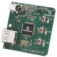
... When running USB device applications, open the jumper J5 to prevent possibly back-feeding voltage onto the V another (or from one host to another). FIGURE 1-1: STARTER KIT LAYOUT (TOP SIDE DS51936B-page Figure 1-1: from one port on the host to BUS © 2010-2011 Microchip Technology Inc. ...
Page 13
... USB Type micro-B receptacle (J4) for USB Device connectivity for dsPIC33E/ PIC24E USB device-based applications. Note: Refer to mapping of device pins to the pins on the expansion connector. FIGURE 1-2: STARTER KIT LAYOUT (BOTTOM SIDE) 2 © 2010-2011 Microchip Technology Inc. Appendix A. “Board Layout and Schematics” 1 for details on the 3 DS51936B-page 13 ...
Page 14
... NOTES: DS51936B-page 14 © 2010-2011 Microchip Technology Inc. ...
Page 15
... Power V or +5V_EXT USB Supply USB Device (Type mini-B) Debugger (PIC24FJ256GB106) Switches LEDs © 2010-2011 Microchip Technology Inc. dsPIC33E/PIC24E USB STARTER KIT USER’S GUIDE Chapter 2. Hardware USB Host Power Supply ICSP™ dsPIC33EP512MU810 (dsPIC33E USB Starter Kit) or PIC24EP512GU810 (PIC24E USB Starter Kit) ...
Page 16
... USB Host using a cable with a type-B micro plug to the starter kit’s micro-B port J4, located on the bottom side of the starter kit. The other end of the cable must have a type-A plug. Connect USB host. Jumper J5 should be removed. DS51936B-page 16 Figure 1-1 for their actual locations on the board. © 2010-2011 Microchip Technology Inc. and ...
Page 17
... Microchip development boards such as the I/O Expansion Board or the Multimedia Expansion Board (MEB), thereby extending the functionality provided by the starter kit. TABLE 2-1: Starter Kit Connector Application Board Connector © 2010-2011 Microchip Technology Inc. STARTER KIT CONNECTOR PART NUMBERS Connector FX10A-120P/12-SV1(71) FX10A-120S/12-SV(71) HIROSE Electric P/N ...
Page 18
... NOTES: DS51936B-page 18 © 2010-2011 Microchip Technology Inc. ...
Page 19
... PIC24E USB Starter Kits and includes the following sections: • Starter Kit Board Layout • Application Hardware Schematics • Starter Kit Debugger Hardware Schematics A.1 STARTER KIT BOARD LAYOUT FIGURE A-1: STARTER KIT BOARD LAYOUT (TOP) © 2010-2011 Microchip Technology Inc. dsPIC33E/PIC24E USB STARTER KIT USER’S GUIDE DS51936B-page 19 ...
Page 20
... FIGURE A-2: STARTER KIT BOARD LAYOUT (BOTTOM) DS51936B-page 20 © 2010-2011 Microchip Technology Inc. ...
Page 21
... A.2 APPLICATION HARDWARE SCHEMATICS FIGURE A-3: TARGET DEVICE (dsPIC33E/PIC24E) R34 4.7K C19 0.1uF 0.1uF © 2010-2011 Microchip Technology Inc 100 RG15 PWML3/PMPD4/RE4 2 99 VDD PWMH2/PMPD3/RE3 3 98 PWMH3/PMPD5/RE5 PWML2/PMPD2/RE2 4 97 PWML4/PMPD6/RE6 RG13 5 96 PWMH4/PMPD7/RE7 RG12 6 95 PWML5/RC1 RG14 7 94 PWMH5/RC2 PWMH1/PMPD1/RE1 8 93 ...
Page 22
FIGURE A-4: POWER DISTRIBUTION/SWITCHING MBR0520L C10 2.2uF R33 0R GND1 D2 U3 +3.3V D4 C12 C13 R29 C11 R30 GREEN 2.2k 200k 0.1uF 0.01uF 2.2uF MCP1727 R31 330 R28 U4 100K OUT 2 GND ...
Page 23
... FIGURE A-5: FIGURE A-6: © 2010-2011 Microchip Technology Inc. USER LEDs R42 D5 330R RED R44 D6 330R YELLOW R46 D7 330R GREEN USER SWITCHES R39 R40 R41 10K 10K 10K DS51936B-page 23 ...
Page 24
... FIGURE A-7: STARTER KIT INTERFACE DS51936B-page 24 © 2010-2011 Microchip Technology Inc. ...
Page 25
FIGURE A-8: USB CONNECTIONS R38 100K R45 100K OUT 2 GND FLAGB R37 FPF2100 200mA Limit 100K (Do not populate OUT 2 GND ...
Page 26
... A.3 STARTER KIT DEBUGGER HARDWARE SCHEMATICS FIGURE A-9: FIGURE A-10: DS51936B-page 26 MINI-ICSP INTERFACE +3.3V R3 10k SERIAL EEPROM +3.3V R11 10k U2 8 VCC SCK HOLD R18 VSS 4 2.2k © 2010-2011 Microchip Technology Inc 1uF ...
Page 27
... FIGURE A-11: TARGET ICSP SIGNALS R13 3.92k R16 2.21k R20 10k R24 10k © 2010-2011 Microchip Technology Inc. R1 330 R2 R4 4.7k 330 R5 330 R6 4.7k R9 R10 100k 10k Q1 MMBT3906 R17 2.21k R14 10k Q2 R19 MMBT3904 100 R21 DNP Q3 MMBT3904 R26 DNP DS51936B-page 27 ...
Page 28
FIGURE A-12: PIC24FJ256GB106 DEBUGGER HOST +3. 0.1uF 0.1uF 0.1uF R7 200k R15 330 +3.3V +3.3V R23 1K R25 3.16K +3.3V C8 R27 1uF 10k +3.3V C1 10uF U1 PIC24FJ256GB106 C9 0.1uF +3.3V +3.3V R12 10k +3.3V C5 ...
Page 29
... NOTES: © 2010-2011 Microchip Technology Inc. DS51936B-page 29 ...
Page 30
... Philippines - Manila Tel: 63-2-634-9065 Fax: 63-2-634-9069 Singapore Tel: 65-6334-8870 Fax: 65-6334-8850 Taiwan - Hsin Chu Tel: 886-3-6578-300 Fax: 886-3-6578-370 Taiwan - Kaohsiung Tel: 886-7-213-7830 Fax: 886-7-330-9305 Taiwan - Taipei Tel: 886-2-2500-6610 Fax: 886-2-2508-0102 Thailand - Bangkok Tel: 66-2-694-1351 Fax: 66-2-694-1350 © 2010-2011 Microchip Technology Inc. 05/02/11 ...