SRP-SIM4 ELESTA, SRP-SIM4 Datasheet - Page 15
SRP-SIM4
Manufacturer Part Number
SRP-SIM4
Description
30M9910
Manufacturer
ELESTA
Datasheet
1.SIM112_16VDC.pdf
(36 pages)
Specifications of SRP-SIM4
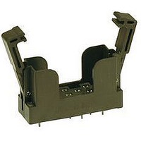
Socket Mounting
PC Board
No. Of Contacts
10
Mounting Type
PC Board
Contact Termination
Solder
Operating Voltage Max
250V
Operating Current Max
7A
Rohs Compliant
Yes


- PCB relay with forcibly guided contacts
- Protective separation between coil and
- EN 50205, type B
- 2 CO contacts
- Mean coil power 1W
- Holding power 0.31 W
2,6
Contact material
Type of contact
Rated switching capacity 250VAC 8A AC1 2’000VA
Electr. life AC1 (360 cycles/h) approx.100’000
Inrush current max.
Switching voltage range
Switching current range*
Switching capacity range* 0.12VA(W) to 2’000VA
Contact resistance (as delivered) <100mΩ/28 V/100mA
* Guide values
Standard coils for direct current
(other voltages on request)
Ordering example
SIR282
Type designation
Coil voltage
Wash-resistant / with O-ring
Relay data
contacts (leakage and creepage distances
> 14mm); protective separation diagonally
between left and right contact side (leakage
and creeping distances > 5.5mm)
110
12
18
24
48
60
5
6
5
5
3,75
13,5
18,0
36,0
45,0
82,5
30,2
4,5
9,0
15
2,5 / 2,54
> 11,0
> 0,5
> 0,6
> 1,2
> 1,8
> 2,4
> 4,8
> 6,0
24VDC 08
2,6
Ø
1,3
181,0
166,0
85,7
66,6
33,3
20,8
13,6
11,0
AgSnO
5 to 250 VDC/VAC
12,7
10’000
Single contact
7,5
2’300
4’400
15A for 20ms
[mm]
27 ,5
140
270
720
36
10mA to 8A
2
+0.2µm Au
1
± 10
± 10
± 10
± 10
± 10
± 10
± 13
± 15
SIR282
Mechanical life
Switching frequency, mechanical
Response time
Drop-out time**
Bounce time of NO contact
Bounce time of NC contact
Vibration resistance 10-55Hz, AK 10g, RK 1.5g
Test voltage coil/contacts
Test voltage
contact set/contact set
Test voltage contact open
Insulation resistance
Creepage resistance
Weight
Mounting position
Ambient temperature
Type of protection
Solder bath temperature
Thermal resistance
Temperature limit for coil
Pollution degree
Resistance to
short circuiting
** without spark suppression
General data
Circuit diagram (view on relay upper side)
Insulation terms
Coil/contacts: Double or reinforced insulation
> 14mm
Left to right contact side:
Double or reinforced insulation > 5.5mm
Tests, regulations
Approvals
UL File E188953
Insulation class IEC 60664-1
Protection class II
Fire protection requirements
Options, accessories
Dust-resistant with O-Ring
Sealed RT III
PCB socket, DIN rail socket
ELESTA relays GmbH, Heuteilstrasse 18,
CH-7310 Bad Ragaz, Switzerland
SIR282
Double or reinforced insulation
RT II / RT III optionally
> 50 x 10
SEV, UL, cUL, TÜV
1‘000A SCPD 10A
5’000Veff 1min
4’000Veff 1min
1’500Veff 1min
-40°C to +70°C
gL/gG (pre-fuse)
typically 12ms
typically 5ms
typically 4ms
typically 8ms
Phone: +41 (0)81 303 54 00
Fax:
6
approx. 20g
see page 29
operations
on request
UL 94 / V1
VDE 0106
270°C/5s
CTI 550
250VAC
50K/W
Sec. 1
120°C
10
+41 (0)81 303 54 01
20Hz
11
any
Ω
2
Max. switching characteristics
(acc. to DIN EN 60947-5-1 table C2):
AC 15: 230V/5A, DC13: 24V/6A; UL 508: C300
Maximal contact load at AC 1 with 230V:
Contact lifetime for NC contact
Max. switching characteristics
(acc. to DIN EN 60947-5-1 table C2):
AC 15: 230V/2A, DC13: 24V/3A
Load limit curve with direct current
1) Inductive load, L/R 40 ms
2) Resistive load
Excitation voltage range
1) Max. excitation voltage with contact load < 2A
No heat accumulation due to intrinsic heating of
other components. Continuous duty 100%.
2 contacts each with 8A
2) Min. excitation voltage (guaranteed values)
Diagrams
Contact lifetime for NO contact
U
U
10 000
10 000
B
N
without previous operation
1000
1000
100
1,5
1,0
0,5
100
2,0
0,8
0,6
0,4
0,3
0,2
0,1
10
10
8
6
4
3
2
1
0
0
0.1
Switching current (A)
Switching current (A)
Voltage (VDC)
0
0.1
Ambient temperature °C
1
E-Mail: admin@elestarelays.com
Internet: http://www.elestarelays.com
50
20
AC 1: 230V
2
AC 15: 230V
1
2
0.5
0.5
100
40
AC 1: 400V
1.0
1.0
AC 15: 230V
150
60
200
AC 1: 230V
DC 13: 24V
80
DC 13: 24V
DC 1: 24V
DC 1: 24V
5.0
5.0
15
100
250
10
10
Related parts for SRP-SIM4
Image
Part Number
Description
Manufacturer
Datasheet
Request
R


Part Number:
Description:
ELESTA RELAY 24 VDC, 10 AMP. 250 VAC
Manufacturer:
AMERICAN ELECTRONIC COMPONENTS


Part Number:
Description:
30M9908
Manufacturer:
ELESTA
Datasheet:

Part Number:
Description:
30M9885
Manufacturer:
ELESTA
Datasheet:
Part Number:
Description:
30M9886
Manufacturer:
ELESTA
Datasheet:

Part Number:
Description:
30M9893
Manufacturer:
ELESTA
Datasheet:

Part Number:
Description:
30M9895
Manufacturer:
ELESTA
Datasheet:
Part Number:
Description:
30M9896
Manufacturer:
ELESTA
Datasheet:
Part Number:
Description:
30M9898
Manufacturer:
ELESTA
Datasheet:
Part Number:
Description:
High Speed Current Mode PWM Control IC for Switching Power Supply
Manufacturer:
Hitachi Semiconductor
Datasheet:
Part Number:
Description:
RS-232C Protocol
Manufacturer:
Sonyoration
Datasheet: