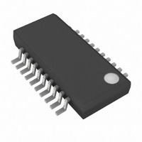
MAX9656AEP+T Maxim Integrated Products, MAX9656AEP+T Datasheet

MAX9656AEP+T
Specifications of MAX9656AEP+T
Related parts for MAX9656AEP+T
MAX9656AEP+T Summary of contents
Page 1
... DC-coupled to a 75Ω load, which is the equivalent of two video loads, or AC-coupled to a 150Ω load. SCART Set-Top Boxes UNKNOWN BIAS ________________________________________________________________ Maxim Integrated Products For pricing, delivery, and ordering information, please contact Maxim Direct at 1-888-629-4642, or visit Maxim’s website at www.maxim-ic.com. Low-Power Video Switches for Dual SCART Connectors ♦ ...
Page 2
Low-Power Video Switches for Dual SCART Connectors ABSOLUTE MAXIMUM RATINGS Supply Voltage V to GND ...........................................................-0.3V to +4V DD All Video and Logic Input Pins..................(GND - 0.3V) to +4V Duration of Output Short Circuit GND ........Continuous DD ...
Page 3
ELECTRICAL CHARACTERISTICS (continued 3.3V VCR_SEL = V SHDN DD GND DD noted. Typical values are +25°C.) (Note 1) A PARAMETER SYMBOL Output Short-Circuit Current Output Resistance Power-Supply Rejection ...
Page 4
Low-Power Video Switches for Dual SCART Connectors (V = 3.3V SHDN DD GND DD SMALL-SIGNAL GAIN vs. FREQUENCY 50mV IN P-P 5 NOTE: GAIN IS NORMALIZED TO 0dB 0 ...
Page 5
SHDN DD GND DD VIDEO PSRR vs. FREQUENCY 3.3V + 100mV DD P-P -10 -20 -30 -40 -50 -60 -70 -80 100k 1M FREQUENCY (Hz) DIFFERENTIAL ...
Page 6
Low-Power Video Switches for Dual SCART Connectors (V = 3.3V SHDN DD GND DD NTC-7 VIDEO TEST SIGNAL 10μs/div VIDEO SYNC-TIP CLAMP VOLTAGE vs. TEMPERATURE 0.40 0.38 0.36 0.34 0.32 0.30 0.28 ...
Page 7
PIN NAME MAX9655 MAX9656 1 2 ENC_B_IN 2 3 ENC_G_IN 3 4 ENC_R_IN 4 5 ENC_CVBS_IN 5 6 VCR_B_IN 6 7 VCR_G_IN 7 8 VCR_R_IN 8 9 VCR_CVBS_IN 9 11 GND 10 13 VCR_CVBS_OUT VCR SCART Composite Video Output. The ...
Page 8
Low-Power Video Switches for Dual SCART Connectors The incoming video signals can have any DC bias because the input sync-tip clamps restore the DC level. The output amplifiers have a gain of 2V/V. The MAX9655/MAX9656 operate from a single 3.3V ...
Page 9
Table 5. MAX9656 Input Circuit of Input as Determined by State of TV_SEL INPUT ENC_B_IN ENC_G_IN ENC_R_IN Sync-tip clamp ENC_CVBS_IN (VCR_SEL = 0) Bias TV_CVBS_IN (VCR_SEL = 0) VCR_B_IN VCR_G_IN VCR_R_IN VCR_CVBS_IN Note: VCR_SEL = X (don’t care), except where ...
Page 10
Low-Power Video Switches for Dual SCART Connectors 12V 0.1μF 7 10μF 4.7kΩ 8 DAC + 300kΩ 1 SDATA 12V 2 DEMSCLK 3 LRCK 5.1kΩ MCLK CS4334 + 5.1kΩ 10μF 10μF 4.7kΩ 5 DAC + 300kΩ 6 12V 10kΩ ...
Page 11
DAC + 300kΩ 1 SDATA 12V 2 DEMSCLK 3 LRCK 5.1kΩ MCLK CS4334 + 5.1kΩ 10μF 4.7kΩ 5 DAC + 300kΩ 6 12V 10kΩ 3.3V TV_SEL 10kΩ TV_SEL 2N3904 JU0 Figure 2. ...
Page 12
Low-Power Video Switches for Dual SCART Connectors Table 6. Quiescent and Average Power Consumption for MAX9655/MAX9656 POWER MEASUREMENTS CONSUMPTION (mW) Quiescent Power 69 Consumption 175 (MAX9655) Average Power Consumption 200 (MAX9656) Power Consumption The quiescent power consumption and average power ...
Page 13
MPEG DECODER TV_SEL GPIO ENC_B_IN B DAC 0.1μF 75Ω G DAC ENC_G_IN R DAC 0.1μF 75Ω CVBS ENC_R_IN DAC 0.1μF 75Ω ENC_CVBS_IN 0.1μF 75Ω VCR_B_IN 0.1μF 75Ω VCR SCART VCR_G_IN 0.1μF 75Ω VCR_R_IN 0.1μF 75Ω VCR_CVBS_IN 0.1μF 75Ω ______________________________________________________________________________________ Low-Power ...
Page 14
Low-Power Video Switches for Dual SCART Connectors MPEG DECODER GPIO GPIO 0.1μF 75Ω B DAC 0.1μF 75Ω G DAC R DAC 0.1μF 75Ω CVBS DAC 0.1μF 75Ω ENC_CVBS_IN 0.1μF 75Ω 0.1μF 75Ω VCR SCART 0.1μF 75Ω 0.1μF 75Ω VCR_CVBS_IN 0.1μF ...
Page 15
Low-Power Video Switches for Dual SCART Connectors TOP VIEW + ENC_B_IN ENC_G_IN 2 15 TV_SEL ENC_R_IN 3 14 TV_B_OUT MAX9655 ENC_CVBS_IN 4 13 TV_G_OUT VCR_B_IN 5 12 TV_R_OUT TV_CVBS_OUT VCR_G_IN 6 11 VCR_R_IN 7 10 VCR_CVBS_OUT ...
Page 16
Low-Power Video Switches for Dual SCART Connectors For the latest package outline information and land patterns www.maxim-ic.com/packages. PACKAGE TYPE 16 QSOP 20 QSOP 16 ______________________________________________________________________________________ Package Information PACKAGE CODE E16-4 E20-1 DOCUMENT NO. 21-0055 21-0055 ...
Page 17
... Maxim cannot assume responsibility for use of any circuitry other than circuitry entirely embodied in a Maxim product. No circuit patent licenses are implied. Maxim reserves the right to change the circuitry and specifications without notice at any time. Maxim Integrated Products, 120 San Gabriel Drive, Sunnyvale, CA 94086 408-737-7600 ____________________ 17 © 2008 Maxim Integrated Products ...


