74ABT74D NXP Semiconductors, 74ABT74D Datasheet
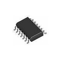
Flip Flops DUAL D-TYPE FLIPFLOP

74ABT74D

Manufacturer Part Number
74ABT74D
Description
Flip Flops DUAL D-TYPE FLIPFLOP
Manufacturer
NXP Semiconductors
Datasheet

Specifications of 74ABT74D

Number Of Circuits
2
Logic Family
ABT
Logic Type
D-Type Edge Triggered Flip-Flop
Polarity
Inverting/Non-Inverting
Input Type
Single-Ended
Propagation Delay Time
3 ns
High Level Output Current
- 15 mA
Supply Voltage (max)
5.5 V
Maximum Operating Temperature
+ 85 C
Mounting Style
SMD/SMT
Package / Case
SOT-108
Minimum Operating Temperature
- 40 C
Supply Voltage (min)
4.5 V
Lead Free Status / Rohs Status
 Details
Other names
74ABT74D,112

Available stocks

Company
Part Number
Manufacturer
Quantity
Price
Part Number:
74ABT74D
Manufacturer:
PHILIPS
Quantity:
8 000
Part Number:
74ABT74D
Manufacturer:
PHILIPS/飞利浦
Quantity:
20 000
Philips Semiconductors
QUICK REFERENCE DATA
PIN CONFIGURATION
PIN DESCRIPTION
LOGIC SYMBOL
ORDERING INFORMATION
1995 Sep 22
SYMBOL
14-Pin Plastic DIP
14-Pin plastic SO
14-Pin Plastic SSOP Type II
14-Pin Plastic TSSOP Type I
PIN NUMBER
V
GND = Pin 7
1, 2, 3, 4, 10,
Dual D-type flip-flop
t
t
CC
t
t
OSLH
OSHL
C
11, 12, 13
I
PLH
PHL
5, 6, 8, 9
CC
= Pin 14
IN
14
7
PACKAGES
Propagation
delay
CPn to
Qn, Qn
Output to
Output skew
Input
capacitance
Total supply
current
PARAMETER
10
13
11
3
4
1
CPn, SDn
SYMBOL
GND
RDn, Dn,
RD1
CP0
SD1
Qn, Qn
Q0
Q0
D0
GND
V
CC
1
2
3
4
5
6
7
CP0
SD0
RD0
CP1
SD1
RD1
Q0 Q0 Q1 Q1
C
V
V
Outputs disabled;
V
5
L
CC
CC
I
CC
Data inputs
Data outputs
Ground (0V)
Positive supply voltage
CONDITIONS
T
= 0V or V
D0 D1
= 50pF;
6
amb
2
GND = 0V
= 5V
= 5.5V
12
NAME AND FUNCTION
9
= 25 C;
TEMPERATURE RANGE
8
14
13
12
11
10
CC
9
8
–40 C to +85 C
–40 C to +85 C
–40 C to +85 C
–40 C to +85 C
V
RD1
D1
CP1
SD1
Q1
Q1
CC
TYPICAL
3.0
2.5
0.5
50
3
SF00045
SA00359
UNIT
ns
ns
pF
A
OUTSIDE NORTH AMERICA
1
DESCRIPTION
The 74ABT74 is a dual positive edge-triggered D-type flip-flop
featuring individual data, clock, set, and reset inputs; also true and
complementary outputs. Set (SD) and reset (RD) are asynchronous
active low inputs and operate independently of the clock input.
When set and reset are inactive (high), data at the D input is
transferred to the Q and Q outputs on the low-to-high transition of
the clock. Data must be stable just one setup time prior to the
low-to-high transition of the clock for predictable operation. Clock
triggering occurs at a voltage level and is not directly related to the
transition time of the positive-going pulse. Following the hold time
interval, data at the D input may be changed without affecting the
levels of the output.
LOGIC SYMBOL (IEEE/IEC)
LOGIC DIAGRAM
74ABT74 PW
74ABT74 DB
V
GND = Pin 7
74ABT74 N
74ABT74 D
CC
= Pin 14
SD
RD
CP
D
4, 10
1, 13
2, 12
3, 11
12
13
10
11
4
3
2
1
NORTH AMERICA
74ABT74PW DH
1D
S
S
R
2D
R
74ABT74 DB
74ABT74 N
74ABT74 D
C1
C2
&
Product specification
74ABT74
DWG NUMBER
853-1813 15793
5
6
9
8
SOT108-1
SOT337-1
SOT402-1
SOT27-1
5, 9
6, 8
SF00047
SF00048
Q
Q

Related parts for 74ABT74D

74ABT74D Summary of contents

Page 1

Philips Semiconductors Dual D-type flip-flop QUICK REFERENCE DATA CONDITIONS SYMBOL PARAMETER amb GND = 0V Propagation t delay PLH CPn 50pF; PHL L Qn Output ...

Page 2

Philips Semiconductors Dual D-type flip-flop FUNCTION TABLE INPUTS OUTPUTS ...

Page 3

Philips Semiconductors Dual D-type flip-flop DC ELECTRICAL CHARACTERISTICS SYMBOL SYMBOL PARAMETER PARAMETER V Input clamp voltage IK V High-level output voltage OH V Low-level output voltage OL I Input leakage current I I Power-off leakage current OFF I Output High ...

Page 4

Philips Semiconductors Dual D-type flip-flop AC WAVEFORMS V = 1.5V GND to 3. The shaded areas indicate when the input is permitted to change for predictable output performance ...

Page 5

Philips Semiconductors Dual D-type flip-flop TEST CIRCUIT AND WAVEFORMS OUT PULSE D.U.T. GENERATOR R T Test Circuit for Outputs DEFINITIONS R = Load resistor; see AC CHARACTERISTICS for value Load capacitance includes ...

Related keywords