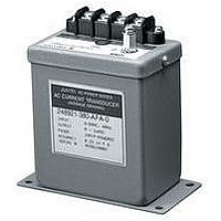
2469-63-54-0-AFB-1-M YOKOGAWA, 2469-63-54-0-AFB-1-M Datasheet - Page 24

2469-63-54-0-AFB-1-M
Manufacturer Part Number
2469-63-54-0-AFB-1-M
Description
63K2357
Manufacturer
YOKOGAWA
Datasheet
1.2489-63-54-0-AHF-1-0-M.pdf
(32 pages)
Specifications of 2469-63-54-0-AFB-1-M
Transducer Function
VAR 3P3W (2 Element)
Supply Voltage Min
100V
Supply Voltage Max
135V
Transducer Input Current Ac
5A
Frequency
60Hz
Supply Voltage
120VAC
Rohs Compliant
NA
P O W E R
T R A N S D U C E R
T E R M I N O L O G Y
Accuracy
The ratio of the error to a standard or true value and expressed as a percent.
Ampere
Unit of electrical current or rate of flow of electrons. One volt across one ohm of resistance causes one ampere
of current flow
ANSI
American National Standards Institute.
Auxiliary Power
The power supplied from an external power source for correct operation of a transducer. (Also see input powered.)
Balanced load
An AC polyphase system where all phase-to-phase voltages, phase currents, and power factors are identical.
Burden
Expressed in Volt-Amperes (VA), and represents the electrical load an instrument or transducer places on
current or potential transformers. Exceeding a CT or PT rated burden affects accuracy.
Calibration
To make precision adjustments to a transducer so that the output is within a specific range for particular
values of the input. High accuracy test equipment is used for verification.
Compliance voltage or Output Compliance
The maximum voltage that a transducer current output can supply and still maintain specified accuracy.
Current transformer
An instrument transformer connected in series with current-carrying conductors for the purpose of measurement
and control. Typically, a CT will step down high current to a level that can be safely measured with an instru-
ment or transducer.
Current transformer ratio (CT ratio ; CTR)
The ratio of primary amps divided by the secondary amps (example: 500A : 5A = 100 : 1).
Element
An electronic circuit in a Watt / Var / Power Factor transducer that accepts a voltage and a current input, then
produces a proportionate analog signal. The number of elements required varies with circuit configuration;
and, if a polyphase circuit, whether it is a balanced load.
Frequency
In electrical terms, it is the measure of complete cycles of a waveform per unit of time and specified as
Hertz(Hz) or cycles per second.
Full scale output
The maximum output value for which the specified accuracy applies (ie, 0.2% accuracy @ 1mA full scale output).
Harmonic
A sinusoidal wave having a frequency that is an integral multiple of the fundamental frequency (Ex: 3rd
harmonic of 60Hz fundamental is 180 Hz). Non-linear loads cause distorted waveforms which create higher
harmonics and heating effect.
Impedance
The vector sum of resistance, inductive reactance and capacitive reactance.
Input
Input voltage and/or current are always specified by the transducer user. For Watt/Var/Power Factor/Phase
Angle transducers, both voltage and current input must be specified. If CT’s and/or PT’s are used, then the
primary and secondary ratings (or ratios) are required for proper calibration of Watts and VARS.
Input powered
This means the transducer is self-powered by the line being measured. (Also see auxiliary power.)
Insulation resistance
The ability of dielectric insulating materials to resist electrical leakage current when a voltage is applied.
Usually specified at a DC voltage level and Megohm value.
Isolation
The electrical separation between various components in a transducer. The measure of strength of a dielectric
system to electrically isolate is usually expressed with various test voltage levels such as 2500VAC, etc.
Lag or Lagging
The current flowing in a circuit lags the applied voltage. This condition indicates a mostly inductive load.
Lead or Leading
The current flowing in a circuit leads the applied voltage. This condition indicates a mostly capacitive load.
22


