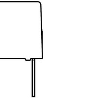
PHE426PF6470JR06L2 Kemet, PHE426PF6470JR06L2 Datasheet

PHE426PF6470JR06L2
Manufacturer Part Number
PHE426PF6470JR06L2
Description
Pulse Film Capacitors 1000volts 0.47uF 5% LS=27.5mm
Manufacturer
Kemet
Specifications of PHE426PF6470JR06L2
Capacitance
0.47 uF
Tolerance
5 %
Voltage Rating
1 KVolts
Lead Spacing
27.5 mm
Termination Style
Radial
Operating Temperature Range
- 55 C to + 105 C
Lead Free Status / Rohs Status
Details
pHE426
• single metallized film pulse capacitor, polypropylene dielectric
• according to iEc 60384-16, grade 1.1
Pulse operation in SMPS, TV, monitor,
electrical ballast and other high frequency
applications demanding stable operation.
rated voltage u
rated voltage u
capacitance range, µf
capacitance values
capacitance tolerance
category temperature range
rated temperature
voltage derating
climatic category
Passive flammability
maximum pulse steepness:
temperature coefficient
self-inductance
dissipation factor tanδ
insulation resistance
tYpiCaL appLiCations
r
r
, vdc
, vac
1 section construction
100
63
0.001
–0.22
In accordance with IEC E12 series
±5%, other tolerances on request
–55 ... +105°C
+85°C
The rated voltage is decreased with 1.3%/°C between +85°C and +105°C.
IEC 60068-1, 55/105/56/B
Category B according to IEC 60065
dU/dt according to article table
For peak to peak voltages lower than rated voltage (U
multiplied by the factor U
–200 (+50, –100) ppm/°C (at 1 kHz)
Approximately 6 nH/cm for the total length of capacitor winding and the leads.
Maximum values at +23°C
1 kHz
10 kHz
100 kHz 0.25%
Measured at +23°C, 100 VDC 60 s for U
Between terminals:
C ≤ 0.33 µF: ≥ 100 000 MΩ
C > 0.33 µF: ≥ 30 000 s
Between terminals and case:
≥ 100 000 MΩ.
Polypropylene film capacitor with vacuum
evaporated aluminum electrodes. Radial
leads of tinned wire are electrically welded
to the contact metal layer on the ends of
the capacitor winding. Encapsulation in
self-extinguishing material meeting the
requirements of UL 94V-0.
Two different winding constructions are
used, depending on voltage and lead
spacing. They are specified in the article
table.
C ≤ 0.1 µF 0.1µF < C ≤ 1.0 µF C > 1.0 µF
250
160
0.001
–27
0.05%
–
300
160
0.033
–18
tECHniCaL data
ConstRuCtion
2 section construction
R
/U
0.05%
0.10%
PP.
–
400
220
0.001
–10
450
220
0.1
–3.9
R
< 500 VDC and at 500 VDC for U
0.10%
–
630
250
0.001
–5.6
PP
< U
1000
250
0.0027
–3.3
10.0 ± 0.4
15.0 ± 0.4
22.5 ± 0.4
27.5 ± 0.4
37.5 ± 0.5
5.0 ± 0.4
7.5 ± 0.4
R
), the specified dU/dt can be
p
p
L
1600
650
0.0047
–0.047
0.5
0.6
0.6
0.8
0.8
0.8
1.0
d
∅ d
R
≥ 500 VDC
std I max I
5
5
5
6
6
6
6
2000
700
0.001
–0.027
0.5
-1
-1
-1
-1
-1
-1
-1
RoHS
Compliant
20
20
30
30
30
30
30
b
B
± 0.4
± 0.4
± 0.4
± 0.4
± 0.4
± 0.4
± 0.7
b
H
l


