9767-22-10-689 Amphenol Industrial Operations, 9767-22-10-689 Datasheet
9767-22-10-689
Specifications of 9767-22-10-689


Related parts for 9767-22-10-689


9767-22-10-689 Summary of contents
Page 1
Amphenol 97 Series Standard Cylindrical Connector 12-022-11 MIL-C-5015 Style Amphenol ...
Page 2
This catalog covers the complete line of Amphenol It is divided into five sections: 97E (Environmental), 97 Series solder, 97 Series crimp, special application connectors, and accessories: Table of Contents ® Amphenol 97 Series Standard Cylindrical Connectors – General Description. ...
Page 3
Amphenol 97 Series Connectors ® provide the interconnection solution for low cost, general duty and environmental applications Amphenol offers the 97 Series Connector Family - A general duty standard cylindrical connec- tor, MIL-C-5015 style, and the recent addi- tion to ...
Page 4
Guide to Selecting a Connector In selecting a connector, it first must be determined if a non-environmental (97 A/B Series) type or an environmental (97E) type is required. Then the following 8 steps apply to formulation of a part number.* ...
Page 5
Amphenol 97E (environmental) series ® Connectors NEW DESIGN FROM AMPHENOL COMBINES AN ENVIRONMENTAL SERVICE CLASS WITH THE COST EFFEC- TIVE BENEFITS OF THE GENERAL DUTY 97 SERIES Amphenol, continuing to meet the needs of today’s interconnection products market- place, now ...
Page 6
Example of part number for environmental 97E Series connectors is given below. (For non-environmental solder type connectors how to order, see pg. 21, and for non-environmental crimp type connectors how to order, see pg. ...
Page 7
Amphenol 97 Series Connectors ® with solder contacts MS3100A MS3101A MS3102A MS3106A MS3106B DESIGN CHARACTERISTICS • Medium to heavy weight cylindrical • Durable, field-proven design • Environmental resistant • Single key/keyway polarization • Threaded coupling, hard dielectric inserts • Operating ...
Page 8
Mechanical Total Service Spacing Insert Number Contacts Rating Inches mm 8S-1 1 1/16 1.57 INST. F 10SL-3 3 1/16 1.57 A 10SL-4 2 1/16 1.57 A 12SL-844 1/16 1.57 A 12S-3 ...
Page 9
Mechanical Insert Total Service Spacing Number Contacts Rating Inches mm 22-26* 7 1/8 3.18 1/8 3.18 D 22-27 9 1/16 1.57 A 22-28† 7 1/16 1.57 A 22-34 5 1/8 3.18 D 24-2 ...
Page 10
Front view of pin insert or rear of socket insert illustrated. Items highlighted are most popular and most readily available. NOTE: Not all insert arrangements are currently available for environmental, individual wire seal. Consult ...
Page 11
Front view of pin insert or rear of socket insert illustrated. Items highlighted are most popular and most readily available. NOTE: Not all insert arrangements are currently available for environmental, individual wire seal. ...
Page 12
Front view of pin insert or rear of socket insert illustrated. Items highlighted are most popular and most readily available. NOTE: Not all insert arrangements are currently available for environmental, individual wire seal. ...
Page 13
Front view of pin insert or rear of socket insert illustrated. Items highlighted are most popular and most readily available. NOTE: Not all insert arrangements are currently available for environmental, individual wire seal. ...
Page 14
Front view of pin insert or rear of socket insert illustrated. Items highlighted are most popular and most readily available. NOTE: Not all insert arrangements are currently available for environmental, individual wire seal. ...
Page 15
Front view of pin insert or rear of socket insert illustrated. Items highlighted are most popular and most readily available. NOTE: Not all insert arrangements are currently available for environmental, individual wire seal. ...
Page 16
FRONT FACE OF PIN INSERT Degrees Insert Arrangement 12S-3 70 145 215 14S-2 – 120 240 14S-5 – 110 – 14S-7 90 180 270 14S-9 70 145 215 16S-1 80 ...
Page 17
MS3100A wall mount receptacle Solid shell construction is strong and con- serves space. Includes integral polarizing key in front. Back shell is threaded for stan- dard MS/AN fittings. MS3100A and MS3101A A K Ref. Connector ...
Page 18
MS3106A L Max. N Ref. Connector Size Inch mm Inch 8S 1-1/4 31.75 17/32 10S 1-5/16 33.32 5/8 10SL 1-3/8 34.93 3/4 12S 1-7/16 36.50 25/32 12 1-7/8 47.63 25/32 12SL 1-31/64 ...
Page 19
MS3106B L Max. Q Max. Connector Size Inch mm Inch 14S 1-11/16 42.85 1-1/8 16S 1-11/16 42.85 1-1/4 18 2-1/16 52.37 1-11/32 20 2-1/8 53.98 1-15/32 22 2-1/8 53.98 1-19/32 24 2-9/32 ...
Page 20
Wall Cable Receptacles Receptacles MS3100 MS3101 Insert Solid Shell Solid Shell Number A A 8S-1 .02 .01 10SL-3P .03 .03 10SL-3S 10SL-4P† .02 .02 10SL-4S† 12S-3 .04 .03 12-5 .05 .04 12S-6* ...
Page 21
Wall Cable Receptacles Receptacles MS3100 MS3101 Insert Solid Shell Solid Shell Number A A 20-4 .14 .13 20-6† .12 .11 20-7 .13 .12 20-8 .15 .14 20-11† .14 .13 20-14 .16 ...
Page 22
Wall Cable Receptacles Receptacles MS3100 MS3101 Insert Solid Shell Solid Shell Number A A 24-11 .24 .22 24-12 .23 .22 24-16 .20 .19 24-19† .18 .17 24-20 .19 .17 24-21 .19 ...
Page 23
Example of part number for non-environmental solder type connectors is given below. (For environmental solder type connectors, see how to order on page 4). 97 – Series Number 97 - Like MS but ...
Page 24
Amphenol 97 Series Connectors ® with rear release crimp contacts 97-4100A 97-4101A 97-4102A 97-4106A 97-4106B DESIGN CHARACTERISTICS • Rugged metal shell • Conductive finish • Stamped & formed crimp contacts • Closed entry socket contacts • Plastic retention • Utilizes ...
Page 25
Specifications Standard shell finish - clear chromate over cadmium plate (optional plating available, see how to order page 29). Inserts - molded of a 94V-O Underwriters Laboratory rated material. Contacts ...
Page 26
Front view of pin insert or rear of socket insert illustrated. 2 Contacts Insert Arrangement 10SL-4 Contacts 2#16 Service Rating A 4 Contacts Insert Arrangement 14S-2 Contacts 4#16 Service Rating INST. 6 Contacts Insert ...
Page 27
Front view of pin insert or rear of socket insert illustrated. 17 Contacts Insert Arrangement 20-29 Contacts 17#16 Service Rating A 30 Contacts Insert Arrangement 32-8 Contacts 6#12, 24#16 Service Rating A Current ...
Page 28
Solid shell construction is strong and con- serves space. Includes integral polarizing key in front. Back shell is threaded for stan- dard MS/AN fittings. 97-4100A and 97-4101A A K Ref. Connector ...
Page 29
L Max. N Ref. Connector Size Inch mm Inch 10SL 1-3/8 34.93 3/4 12S 1-7/16 36.50 25/32 14S 1-15/32 37.13 7/8 16S 1-15/32 37. 1-31/32 49.88 1-1/8 20 1-7/8 ...
Page 30
L Max. Q Max. Connector Size Inch mm Inch 14S 1-11/16 42.85 1-1/8 16S 1-11/16 42.85 1-1/4 18 2-1/16 52.37 1-11/32 20 2-1/8 53.98 1-15/32 22 2-1/8 53.98 1-19/32 24 2-9/32 ...
Page 31
Example of part number for non-environmental crimp type connectors is given below. (For environmental crimp type connectors, see how to order on page 4 4101 Series Number 97 - designates AMPHENOL ...
Page 32
Crimp contacts can be ordered for 97 Series connectors in reel assemblies or in bulk packaging. Order by part numbers given below: Reel Assembly - For use with semi-automatic crimping equipment; order number of ...
Page 33
Insert Contact Contact Arrangement Quantity Size 10SL 10SL 12S 14S 14S 14S 14S 16S 16S-8 5 ...
Page 34
Potting (438 Construction) Potting constructions actually exceed the Type “E” requirements of military specifications for moisture-proof connectors. These con- structions replace the back shell completely with a lightweight threaded retainer ring permanently staked to the ...
Page 35
Box Type Plugs (97-5105 construction) Mounts directly on box or housing. For direct connection of two pieces of equipment with- out interconnecting wires. Available in all sizes; male or female inserts. To order, com- plete ...
Page 36
ECG Connectors For ECG monitoring cable and equipment. Meets requirements of ECG connector stan- dard draft by A.A.M.I. (Association for the Advancement of Medical Instrumentation). Standard number in A.A.M.I. ECGC-D 10/75. Note: This connector is ...
Page 37
Cable Clamp MS3057A Type For jacketed cable or wires protected by tubing. Both clamping halves float for maximum strain relief. For unjacketed cable or wires, use corre- sponding MS3420 bushing. To order clamp with ...
Page 38
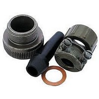
... Cable Clamp for AN fittings In selecting a cable clamp for a connection with AN fittings, the 9767 clamp with the adapter may be used. Max O.D. Cable A B Inch mm Inch mm Inch mm 1/2 12.70 1-13/16 30 ...
Page 39
Caps and Chain Assemblies Fit MS and 97 type receptacles and plugs; provide protection against live circuits and keep out dirt and dust when connector is not in use. Two styles are available: ...
Page 40
Polyethylene Protective Dust Caps Expendable polyethylene dust caps provide added protection for connectors during storage and handling, in assembling with other equipment, and after com- plete assembly into a finished apparatus. Protective caps ...
Page 41
Adapter Used as reducing or extending bushing. Note: 97-3055 supersedes part number AN-3055. Conduit Size AN Number Inch mm 97-3055-12-4 1/4 6.35 97-3055-14-4 97-3055-14-6 3/8 9.53 97-3055-16-6 97-3055-18-6 97-3055-16-8 1/2 12.70 97-3055-18-8 97-3055-22-8 97-3055-18-10 ...
Page 42
Conduit Box Connector Used with AN3066 locknut to form termination at con- duit boxes or panel. May be used with AN3057 clamp to relieve strain on wiring cable terminals. Note: ...
Page 43
The Amphenol plain flat gasket of synthetic rubber material is provided to take advantage of waterproof and pressure sealing features for use with the flange mounted receptacle. This flat gasket is provided ...
Page 44
Dummy Receptacle Shells Same as MS receptacle less insert and contacts. Used to anchor MS plugs when not in use. For A Amphenol Connector Part Number Size Inch mm Inch 10S 97-181-10S .562 14.27 ...