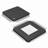
MAX4814EECB+T Maxim Integrated Products, MAX4814EECB+T Datasheet - Page 12

MAX4814EECB+T
Manufacturer Part Number
MAX4814EECB+T
Description
IC SW DVI/HDMI 2:4 BIDIR 64-TQFP
Manufacturer
Maxim Integrated Products
Series
4000r
Datasheet
1.MAX4814EECB.pdf
(17 pages)
Specifications of MAX4814EECB+T
Function
Switch
Circuit
1 x 2:4
On-state Resistance
12 Ohm
Voltage Supply Source
Single Supply
Voltage - Supply, Single/dual (±)
4.5 V ~ 5.5 V
Current - Supply
10µA
Operating Temperature
-40°C ~ 85°C
Mounting Type
Surface Mount
Package / Case
64-TQFP Exposed Pad
Lead Free Status / RoHS Status
Lead free / RoHS Compliant
For example: If AD0, AD1, and AD2 are hardwired to
ground, then the complete address is 0111000. The full
address is defined as the seven most significant bits
followed by the read/write bit. Set the read/write bit to 1
to configure the MAX4814E to read mode. Set the
read/write bit to 0 to configure the MAX4814E to write
mode. The address is the first byte of information sent
to the MAX4814E after the START condition.
.
As with all Maxim devices, ESD-protection structures
are incorporated on all pins to protect against electro-
static discharges encountered during handling and
assembly. Switch A, switch B, and switch SW_ are fur-
ther protected against static electricity. Maxim’s engi-
neers have developed state-of-the-art structures to
protect these pins against ESD up to ±6kV without
DVI/HDMI 2:4 Low-Frequency Fanout Switch
X = Don’t care.
X = Hardwired, not programmed by user.
12
Table 4. I
Table 5. I
MODE
PIN
______________________________________________________________________________________
1
1
1
1
1
1
1
1
1
1
1
1
BBEN
BIT 7
2
2
C Register R1 (0X01) to DO_ Mapping
BIT 7
C Register R0 (0x00)
—
—
—
—
—
—
—
—
—
0
0
1
Applications Information
BBSEL1
BIT 6
BIT 6
—
—
—
—
—
—
—
—
—
X
0
1
BBSEL0
BIT 5
BIT 5
—
—
—
—
—
—
—
—
—
ESD Protection
0
0
1
REGISTER R1 (0x01)
BIT 4
—
—
—
—
—
—
—
—
—
0
1
X
BAEN
REGISTER R0 (0x00)
BIT 4
BIT 3
—
—
—
—
—
—
—
—
—
0
0
1
damage. The ESD structures withstand high ESD in
normal operation, and when the device is powered
down. ESD protection can be tested in various ways.
The ESD protection of switch A, switch B, and switch
SW_ are characterized for ±6kV (Human Body Model)
using the MIL-STD-883.
ESD performance depends on a variety of conditions.
Contact Maxim for a reliability report that documents
test setup, test methodology, and test results.
Figure 7 shows the Human Body Model, and Figure 8
shows the current waveform it generates when dis-
charged into a low impedance. This model consists of a
100pF capacitor charged to the ESD voltage of interest
that is then discharged into the test device through a
1.5kΩ resistor.
BASEL1
BIT 3
BIT 2
—
—
—
—
—
—
—
—
—
0
1
X
BASEL0
BIT 1
BIT 2
—
—
—
—
—
—
—
—
—
0
0
1
BIT 0
—
—
—
—
—
—
—
—
—
X
0
1
ESD Test Conditions
Human Body Model
BIT 1
X
CONFIGURATION
DO0
DO0
DO0
DO1
DO1
DO1
DO2
DO2
DO2
DO3
DO3
DO3
OUTPUT PIN
BIT 0
X
Hi-Z
Hi-Z
Hi-Z
Hi-Z
0
1
0
1
0
1
0
1


