HR1S-AC5121 IDEC, HR1S-AC5121 Datasheet
HR1S-AC5121
Specifications of HR1S-AC5121


Related parts for HR1S-AC5121


HR1S-AC5121 Summary of contents
Page 1
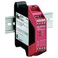
... Turns on when power circuit is normal. Turns off when power is interrupted or the electronic fuse blows. • K1: Turns on when K1 relay operates. • K2: Turns on when K2 relay operates. The HR1S-AC5121P terminal block can be removed and installed as shown, allow- ing for easy installation and replacement of modules × 0.75mm maximum ...
Page 2
... Safety Category 3 Example Circuit (using an emergency stop switch with 2NC contacts) F1 Fuse (+) ( HR1S-AC LOGIC + A1/A2 K1/K2 T – (–) Safety Category 1 Example Circuit (using an emergency stop switch with 1NC contact) L1 (+) F1 Fuses: 4A (gL) ( HR1S-AC + LOGIC A1/A2 K1/K2 T – (–) Output Contact Electrical Life 100 AC15: 230V DC13: 24V ESC +24V DC ...
Page 3
... HR1S-AC Safety Relay Module Operation Chart When Using a Start Switch Power ON Emergency Stop Switch A1 (NC1) Emergency Stop Switch A2 Start Switch Operated (NC2) OFF Feedback Circuit with Start Switch (Y1-Y2) Output 13-14 (NO Contact) Output 23-24 (NO Contact) Output 33-34 (NO Contact) Transistor Output Y43-Y44 (NO Contact) ...