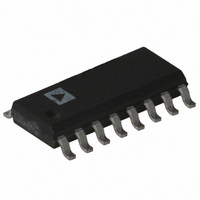
ADG713BR-REEL7 Analog Devices Inc, ADG713BR-REEL7 Datasheet - Page 7

ADG713BR-REEL7
Manufacturer Part Number
ADG713BR-REEL7
Description
IC SWITCH QUAD SPST 16SOIC
Manufacturer
Analog Devices Inc
Datasheet
1.ADG711BRUZ.pdf
(12 pages)
Specifications of ADG713BR-REEL7
Rohs Status
RoHS non-compliant
Function
Switch
Circuit
4 x SPST - NC/NO
On-state Resistance
4 Ohm
Voltage Supply Source
Single Supply
Voltage - Supply, Single/dual (±)
1.8 V ~ 5.5 V
Current - Supply
0.001µA
Operating Temperature
-40°C ~ 85°C
Mounting Type
Surface Mount
Package / Case
16-SOIC (0.154", 3.90mm Width)
Available stocks
Company
Part Number
Manufacturer
Quantity
Price
Company:
Part Number:
ADG713BR-REEL7
Manufacturer:
SEMTECH
Quantity:
1 758
APPLICATIONS
Figure 9 illustrates a photodetector circuit with programmable
gain. An AD820 is used as the output operational amplifier.
With the resistor values shown in the circuit, and using different
combinations of the switches, gain in the range of 2 to 16 can be
achieved.
REV. A
–2
–4
–6
0
10k
Figure 7. On Response vs. Frequency
V
DD
= 5V
100k
FREQUENCY (Hz)
1M
(MSB) IN4
Figure 9. Photodetector Circuit with Programmable Gain
(LSB) IN1
D1
IN2
IN3
10M
+2.5V
100M
C1
S1
S2
S3
S4
33k
R1
GND
+5V
D1
D2
D3
D4
GAIN RANGE 2 TO 16
–7–
240k
120k
R4
R6
120k
120k
120k
R10
R8
R9
240k
120k
R5
R7
Figure 8. Charge Injection vs. Source Voltage
+5V
–10
25
20
15
10
–5
5
0
0
AD820
T
A
0.5
= 25 C
R2
510k
R3
510k
1.0
ADG711/ADG712/ADG713
V
V
+2.5V
1.5
DD
OUT
SOURCE VOLTAGE (V)
= 3V
2.0
2.5
3.0
3.5
V
DD
= 5V
4.0
4.5
5.0


