DFLS240-7 Diodes Zetex, DFLS240-7 Datasheet
DFLS240-7
Specifications of DFLS240-7
Available stocks


Related parts for DFLS240-7


DFLS240-7 Summary of contents
Page 1
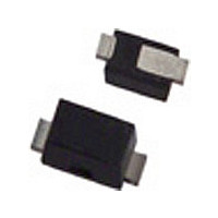
... A Symbol Min Typ ⎯ (BR)R ⎯ 0. ⎯ 0.65 ⎯ ⎯ ⎯ ⎯ ⎯ pad layout 25° www.diodes.com DFLS240 PowerDI ® 123 Value Unit 2 Typ Max Unit ⎯ 73 °C/W ⎯ 13 °C/W -65 to +125 °C -65 to +150 °C Max Unit Test Condition ⎯ ...
Page 2
... Fig. 1 Typical Forward Characteristics 1,000 100 10 1 REVERSE VOLTAGE (V) R Fig. 3 Total Capacitance vs. Reverse Voltage Ordering Information (Note 5) Part Number DFLS240-7 Notes: 5. For packaging details our website at http://www.diodes.com/datasheets/ap02007.pdf. Marking Information Date Code Key Year 2003 2004 Code P R Month Jan Feb ...
Page 3
... Dimensions IMPORTANT NOTICE LIFE SUPPORT www.diodes.com DFLS240 ® PowerDI 123 3.50 3.90 3.70 2.60 3.00 2.80 1.63 1.93 1.78 0.93 1.00 0.98 0.85 1.25 1.00 0.15 0.25 0.20 0.55 0.75 0.65 1.80 2.20 2.00 0.95 1.25 1.10 Value (in mm) 1.0 2.2 ...