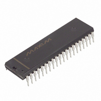
DS2180A+ Maxim Integrated Products, DS2180A+ Datasheet - Page 11

DS2180A+
Manufacturer Part Number
DS2180A+
Description
IC TRANSCEIVER T1 40-DIP
Manufacturer
Maxim Integrated Products
Datasheet
1.DS2180A.pdf
(35 pages)
Specifications of DS2180A+
Function
Transceiver
Interface
T1
Number Of Circuits
1
Voltage - Supply
4.5 V ~ 5.5 V
Current - Supply
3mA
Operating Temperature
0°C ~ 70°C
Mounting Type
Through Hole
Package / Case
40-DIP (0.600", 15.24mm)
Includes
Alarm Generation and Detection, B7 Stuffing Mode, B8ZS Mode, Error Detection and Counter, "Hardware" Mode, Transparent Mode
Product
Framer
Number Of Transceivers
1
Supply Voltage (max)
5.5 V
Supply Voltage (min)
4.5 V
Supply Current (max)
10 mA
Maximum Operating Temperature
+ 70 C
Minimum Operating Temperature
0 C
Mounting Style
Through Hole
Lead Free Status / RoHS Status
Lead free / RoHS Compliant
Power (watts)
-
Lead Free Status / Rohs Status
Lead free / RoHS Compliant
193S TRANSMIT MULTIFRAME TIMING Figure 9
NOTES:
1. Transmit frame and multiframe timing may be established in one of four ways:
2. Channels in which robbed bit signaling is enabled will sample TABCD during the LSB bit time in
3. When external S-bit insertion is enabled, TLINK will be sampled during the F-bit time of even frames
a. With TFSYNC tied low, TMSYNC may be pulsed high once every multiframe period to establish
b. TFSYNC may be pulsed every 125 microseconds; pulsing TMSYNC once establishes multiframe
c. TMSYNC and TFSYNC may be continuously pulsed to establish and reinforce frame and
d. If TMSYNC is tied low and TFSYNC is pulsed at frame boundaries, the transmitter will establish
frames indicated.
and inserted into the outgoing data stream.
multiframe boundaries, allowing internal counters to determine frame timing.
boundaries.
superframe timing.
an arbitrary multiframe boundary as indicated by TMO.
11 of 35
DS2180A


