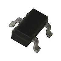
HSMS2850BLK Avago Technologies US Inc., HSMS2850BLK Datasheet

HSMS2850BLK
Specifications of HSMS2850BLK
Related parts for HSMS2850BLK
HSMS2850BLK Summary of contents
Page 1
HSMS-285x Series Surface Mount Zero Bias Schottky Detector Diodes Data Sheet Description Avago’s HSMS-285x family of zero bias Schottky detector diodes has been designed and optimized for use in small signal (Pin <-20 dBm) applications at frequencies below 1.5 GHz. ...
Page 2
SOT-23/SOT-143 DC Electrical Specifications, T Part Package Number Marking Lead HSMS- Code Code 2850 P0 0 2852 P2 2 2855 P5 5 Unconnected Pair Test Conditions Notes: 1. ∆VF for diodes in pairs is 15.0 mV maximum at 1.0 mA. ...
Page 3
Absolute Maximum Ratings +25°C, Single Diode C Symbol Parameter P Peak Inverse Voltage IV T Junction Temperature J T Storage Temperature STG T Operating Temperature OP θ Thermal Resistance [2] jc Notes: 1. Operation in excess of any ...
Page 4
Typical Parameters, Single Diode 100 10 1 0.1 0.01 0 0.2 0.4 0.6 0.8 1.0 1.2 1.4 1.6 1.8 V – FORWARD VOLTAGE (V) F Figure 1. Typical Forward Current vs. Forward Voltage. 3.1 FREQUENCY = 2.45 GHz 2.9 P ...
Page 5
Applications Information Introduction Avago’s HSMS-285x family of Schottky detector diodes has been developed specifically for low cost, high volume designs in small signal (P in tions at frequencies below 1.5 GHz. At higher frequen- cies, the DC biased HSMS-286x family ...
Page 6
perhaps the easiest to measure accurately. The V curve is measured for the diode under forward bias, and the slope of the curve is taken ...
Page 7
The most difficult part of the design of a detector circuit is the input impedance matching network. For very broadband detectors, a shunt 60 Ω resistor will give good input match, but at the expense of detection sensitivity. When maximum ...
Page 8
Such a circuit offers several advantages. First the voltage outputs of two diodes are added in series, increasing the overall value of voltage sensitivity for the network (com- pared to a single diode detector). Second, the RF imped- ances of ...
Page 9
SMT Assembly Reliable assembly of surface mount components is a complex process that involves many material, process, and equipment factors, including: method of heating (e.g vapor phase reflow, wave soldering, etc.) circuit board material, conductor thickness and pattern, ...
Page 10
Part Number Ordering Information No. of Part Number Devices HSMS-285x-TR2G 10000 HSMS-285x-TR1G 3000 HSMS-285x-BLK G 100 where and P for HSMS-285x. Package Dimensions Outline 23 (SOT-23 XXX ...
Page 11
Outline 143 (SOT-143 XXX SYMBOL A A1 Notes: XXX-package marking Drawings are not to scale Device Orientation REEL CARRIER TAPE USER FEED DIRECTION COVER TAPE For Outline SOT-143 TOP VIEW 4 mm ...
Page 12
Tape Dimensions and Product Orientation For Outline SOT- 9° MAX A 0 DESCRIPTION SYMBOL SIZE (mm) 3.15 ± 0.10 CAVITY LENGTH A 0 WIDTH B 2.77 ± 0.10 0 1.22 ± 0.10 DEPTH K ...
Page 13
Tape Dimensions and Product Orientation For Outlines SOT-323, -363 DESCRIPTION SYMBOL CAVITY LENGTH A 0 WIDTH B 0 DEPTH K 0 PITCH P BOTTOM HOLE DIAMETER D 1 PERFORATION DIAMETER D PITCH ...


