PWR263S-35-R750FE Bourns Inc., PWR263S-35-R750FE Datasheet

Current Sense Resistors - SMD 0.75Ohms 1% 250V

PWR263S-35-R750FE

Manufacturer Part Number
PWR263S-35-R750FE
Description
Current Sense Resistors - SMD 0.75Ohms 1% 250V
Manufacturer
Bourns Inc.
Series
PWR263S-35r
Type
Power Resistorr
Datasheet

Specifications of PWR263S-35-R750FE

Resistance
0.75 Ohms
Power Rating
35 Watts
Tolerance
1 %
Temperature Coefficient
+/- 100 PPM / C
Package / Case
D2Pak
Product
Thick Film Resistors SMD
Operating Temperature Range
- 55 C to + 155 C
Dimensions
10.1 mm W x 15.39 mm L x 4.5 mm H
Termination Style
SMD/SMT
Voltage Rating
250 Volts
Lead Free Status / Rohs Status
 Details
Bourns
is used in current measurement, snubber, bleeder and discharge circuits.
*RoHS Directive 2002/95/EC Jan 27, 2003 including Annex.
Specifi cations are subject to change without notice.
Customers should verify actual device performance in their specifi c applications.
** Available for most values. Check Standard Resistance Values table.
Parameter
Resistance
(See table of standard values)
Power Rating @ 25 ˚C Case Temperature
Tolerance
TCR
Thermal Resistance - R thj
Inductance
Operating Voltage
Dielectric Strength
Insulation Resistance
Operating Temperature
Parameter
Short Term Overload (2x Pr for R < 2 Ω,
1.6 x Pr for R ≥ 2 Ω, V < 1.5 x Operating Voltage)
Load Life (1000 hours at rated power)
Thermal Shock (-55 ˚C to 155 ˚C, 5 cycles)
Resistance to Soldering Heat (10 seconds at 270 ˚C)
Vibration (20 G 10-2000 Hz .06 ” D.A.)
Moisture Sensitivity Level
Derating Curve
General Information
Electrical & Thermal Characteristics
Reliability Characteristics
0.02 Ω<R<130.0K Ω
®
PWR263S-35 Series is a TO263 DPAK style power resistor. Manufactured using thick fi lm on alumina ceramic technology, it
120
100
80
60
40
20
0
25
50
Temperature of Backplate (°C)
85
100
PWR263S-35 Series Power Resistor
Features
115
D
Low inductance
Resistor electrically isolated from the
backplate
High power rating
Compatible with lead free solder refl ow
temperatures
2
PAK housing
Specifi cation
ΔR
ΔR
ΔR
ΔR ±0.5 %
ΔR ±0.25 %
1
130
Value(s)
0.02 Ω to 130 KΩ
35 W
±1 %**,
±100 PPM/˚C
3.7 ˚C/W
0.1 µH maximum
√P*R with a maximum of 250 V
2 KV AC
10 GΩ
-55 ˚C to 155 ˚C
±0.25 %
±1.0 %
±0.5 %
145
±5 %
155
Applications
Resistor .................................. Thick fi lm
Substrate ......................Alumina (AL203)
Housing ........................................Epoxy
Pins ....................Tinned Copper (Sn/Cu)
Flammability ........Conforms to UL-94V0
*** 5 % Tolerance
RESISTANCE
CODE
MANUFACTURER'S
TRADEMARK
Code
R020
R050
R100
R500
R750
1R00
1R50
2R00
2R20
2R50
3R00
3R30
4R70
5R00
7R50
8R20
10R0
15R0
RoHS compliant*
Power supplies
Motor drives
Test and measurement
Rectifi ers
Material Characteristics
Standard Resistance Values
Typical Part Marking
Resistance
0.02***
0.05***
Value
0.75
0.1
0.5
1.5
2.2
2.5
3.3
4.7
7.5
8.2
10
15
1
2
3
5
XXXX
COSTA RI CA
263 35
Code
20R0
30R0
33R0
47R0
50R0
56R0
75R0
1000
2000
3300
4700
7500
1001
3301
1002
3002
1003
1303
YYY
X%
Resistance
100000
130000
10000
33000
Value
7500
1000
3300
100
200
330
470
MODEL
NUMBER
TOLERANCE
DATE CODE
COUNTRY
OF ORIGIN
20
30
33
47
50
56
75

Related parts for PWR263S-35-R750FE

PWR263S-35-R750FE Summary of contents

Page 1

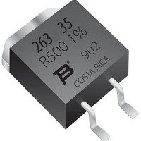
... General Information ® Bourns PWR263S-35 Series is a TO263 DPAK style power resistor. Manufactured using thick fi alumina ceramic technology used in current measurement, snubber, bleeder and discharge circuits. Electrical & Thermal Characteristics Parameter Resistance (See table of standard values) Power Rating @ 25 ˚C Case Temperature ...

Page 2

... PWR263S-35 Series Power Resistor Product Dimensions 10.1 (0.398) 1.6 7.8 (0.063) (0.307) 48 ° 10.4 (0.409) REF. 8.8 (0.347) 1.4 (0.055) 5.08 (0.20) Soldering Profi le 275 <1> Maximum of 20 seconds between +245 °C and +260 °C 225 190 °C 175 150 °C ...

Page 3

... PWR263S-35 Series Power Resistor Pulse Power Rating 100 10 1 0.1 0. The energy absorbed by the resistor expressed in Joules can be calculated by multiplying the peak power of the pulse in watts times the length of the pulse in seconds. The energy should not exceed the limits shown in the graph. The overload voltage should not exceed 1.5 times the maximum operating voltage. Packaging Specifi ...

Related keywords