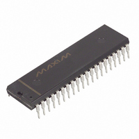
DS2180A Maxim Integrated Products, DS2180A Datasheet - Page 27

DS2180A
Manufacturer Part Number
DS2180A
Description
IC TRANSCEIVER T1 40-DIP
Manufacturer
Maxim Integrated Products
Datasheet
1.DS2180A.pdf
(35 pages)
Specifications of DS2180A
Function
Transceiver
Interface
T1
Number Of Circuits
1
Voltage - Supply
4.5 V ~ 5.5 V
Current - Supply
3mA
Operating Temperature
0°C ~ 70°C
Mounting Type
Through Hole
Package / Case
40-DIP (0.600", 15.24mm)
Includes
Alarm Generation and Detection, B7 Stuffing Mode, B8ZS Mode, Error Detection and Counter, "Hardware" Mode, Transparent Mode
Lead Free Status / RoHS Status
Contains lead / RoHS non-compliant
Power (watts)
-
Available stocks
Company
Part Number
Manufacturer
Quantity
Price
Part Number:
DS2180A
Manufacturer:
DALLAS
Quantity:
20 000
Company:
Part Number:
DS2180A+
Manufacturer:
Exar
Quantity:
207
Company:
Part Number:
DS2180AQ
Manufacturer:
DALLAS
Quantity:
5 510
Part Number:
DS2180AQ
Manufacturer:
DALLAS
Quantity:
20 000
Company:
Part Number:
DS2180AQ+
Manufacturer:
Maxim Integrated Products
Quantity:
135
Company:
Part Number:
DS2180AQ+
Manufacturer:
Maxim
Quantity:
24
Company:
Part Number:
DS2180AQ+T&R
Manufacturer:
Maxim Integrated
Quantity:
10 000
repeating pattern ...00111000111000...(00111X0 if CCR.3–YELMD–is equal to a 1). In this mode, F
and F
causes the synchronizer to search for F
sync will be established using the F
F
alignment, RLOS will go low, and a false multiframe position may be indicated by RMSYNC. RFER will
indicate when the received S-bit pattern does not match the assumed internal multiframe alignment. This
mode will be used in applications where non-standard S-bit patterns exist. In such applications,
multiframe alignment information can be decoded externally by using the S-bits present at RLINK.
AVERAGE REFRAME TIME
NOTE:
1. Average Reframe Time is defined here as the average time it takes from the start of sync (rising edge
BACKPLANE INTERFACE USING DS2180A AND DS2176 Figure 22
S
FRAME
MODE
information is present. If no valid F
of RLOS) to the actual loading of the new alignment (on a multiframe edge) into the output receive
timing.
193S
193E
S
patterns must be correctly identified by the synchronizer before sync is declared. Clearing RCR.3
MIN
3.0
6.0
RCR.2=0
AVG
3.75
7.5
T
1
information, while multiframe sync will be established only if valid
T
Table 9
patterns (101010...) without cross-coupling the F
S
MAX
pattern is identified, the synchronizer will move to the F
4.5
9.0
27 of 35
MIN
13.0
6.5
RCR.2=1
AVG
7.25
14.5
MAX
16.0
8.0
S
pattern. Frame
UNITS
DS2180A
ms
T
T


