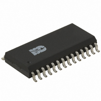
ISD1416S Nuvoton Technology Corporation of America, ISD1416S Datasheet - Page 6

ISD1416S
Manufacturer Part Number
ISD1416S
Description
IC VOICE REC/PLAY 16S 28-SOIC
Manufacturer
Nuvoton Technology Corporation of America
Series
ISD1400r
Datasheet
1.ISD1416P.pdf
(33 pages)
Specifications of ISD1416S
Interface
Pushbutton
Filter Pass Band
3.3kHz
Duration
16 Sec
Mounting Type
Surface Mount
Package / Case
28-SOIC (0.300", 7.50mm Width)
Lead Free Status / RoHS Status
Contains lead / RoHS non-compliant
Available stocks
Company
Part Number
Manufacturer
Quantity
Price
Company:
Part Number:
ISD1416S
Manufacturer:
TI
Quantity:
6 323
Part Number:
ISD1416S
Manufacturer:
ISD
Quantity:
20 000
Part Number:
ISD1416SI
Manufacturer:
ISD
Quantity:
20 000
Company:
Part Number:
ISD1416SY
Manufacturer:
XILINX
Quantity:
101
Part Number:
ISD1416SY
Manufacturer:
ISD
Quantity:
20 000
5. PIN DESCRIPTION
PIN NAME
V
V
SP+, SP-
CCA
SSD
A0-A7
MIC
NC
, V
, V
CCD
SSA
7, 8, 11, 22
1-6, 9, 10
PIN NO
12, 13
14, 15
16, 28
17
Address Inputs: The address inputs have two functions,
depending on the level of the two Most Significant Bits (MSB)
of the address.
If either or both of the two MSBs are LOW, the inputs are all
interpreted as address bits and are used as the start address
for the current record or playback cycle. The address pins are
inputs only and do not output internal address information as
the operation progresses. Address inputs are latched by the
falling edge of PLAYE , PLAYL , or REC .
If both A6 & A7 are HIGH, then the device is in special
operational modes. Please refer to operational modes section
for details.
NC: No Connect
Ground : Similar to V
circuits internal to the ISD1400 series use separate ground
buses to minimize noise. These pins should be tied together
as close as possible to the device.
Speaker Outputs : The SP+ and SP- pins provide direct drive
for loudspeakers with impedances as low as 16 Ω. A single
output may be used, but, for direct-drive loudspeakers, the
two opposite-polarity outputs provide an improvement in
output power of up to four times over a single-ended
connection. Forthermore, when SP+ and SP- are used, a
speakercoupling capacitor is not required. A single-ended
connection will require an AC-coupling capacitor between the
SP pin and the speaker. The speaker outputs are in a high-
impedance state during a record cycle, and held at V
during power down.
Supply Voltage : Analog and digital circuits internal to the
ISD1400 series use separate power buses to minimize noise
on the chip. These voltage buses are brought out to separate
pins on the package and should be tied together as close to
the supply as possible. It is important that the power supply
be decoupled as close to the package as possible.
Microphone : The microphone input transfers its signal to the
on-chip preamplifier. An on-chip Automatic Gain Control
(AGC) circuit controls the gain of this preamplifier from –15 to
24dB. An external microphone should be AC coupled to this
pin via a series capacitor. The capacitor value, together with
the internal 10 KΩ resistance on this pin, determines the low-
frequency cutoff for the ISD1400 series passband. See
Winbond’s Application Information for additional information
on low-frequency cutoff calculation.
- 6 -
CCA
FUNCTION
and V
CCD
ISD1400 SERIES
, the analog and digital
SSA


