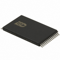
ISD5008EIR Nuvoton Technology Corporation of America, ISD5008EIR Datasheet - Page 9

ISD5008EIR
Manufacturer Part Number
ISD5008EIR
Description
IC VOICE REC/PL 4-8MIN IN 28TSOP
Manufacturer
Nuvoton Technology Corporation of America
Series
ISD5008r
Datasheet
1.ISD5008E.pdf
(47 pages)
Specifications of ISD5008EIR
Interface
SPI/Microwire
Filter Pass Band
1.7 ~ 3.4kHz
Duration
4 ~ 8 Min
Mounting Type
Surface Mount
Package / Case
28-TSOP
For Use With
ISD-ES511 - EVALUATION SYSTEM FOR ISD5100ISD-ES501 - EVALUATION SYSTEM FOR ISD5008
Lead Free Status / RoHS Status
Contains lead / RoHS non-compliant
ISD5008 Product
ANAOUT+/–
This differential output is designed to go to the mi-
crophone input of the telephone chip set. It is de-
signed to drive a minimum of 5 kΩ between the
“+” and “–” pins to a nominal voltage level of
700 mVp-p. Both pins have DC bias of approxi-
mately 1.2 VDC. The AC signal is superimposed
upon this analog ground voltage. These pins can
be used single-ended, getting only half the volt-
age. Do NOT ground the unused pin.
AUX OUT
The AUXOUT is an additional audio output pin, to
be used, for example, to drive the speaker circuit
in a “car kit.” It drives a minimum load of 5 kΩ and
up to a maximum of 1 Vp-p. The AC signal is su-
perimposed on approximately 1.2 VDC bias and
must be capacitively coupled to the load.
SP+, SP–
This is the speaker differential output circuit. It is de-
signed to drive an 8 Ω speaker connected across
the speaker pins up to a maximum of 23.5 mW
power. This stage has two selectable gains, 1.32
and 1.6, which can be chosen through the con-
figuration registers. These pins are biased to ap-
proximately 1.2 VDC and, if used single-ended,
must be capacitively coupled to their load. Do
NOT ground the unused pin.
ACAP
This pin provides the capacitor connection for
setting the parameters of the microphone AGC
circuit. It should have a 4.7 µF capacitor con-
nected to ground. It cannot be left floating. This is
because the capacitor is also used in the
playback mode for the AutoMute circuit. This
circuit reduces the amount of noise present in the
output during quiet pauses. Tying this pin to
ground gives maximum gain; to V
minimum gain for the AGC amplifier but will
cancel the AutoMute function.
6
(Auxiliary Output)
(Speaker+/–)
(AGC Capacitor)
(Analog Outputs)
CCA
gives
2.3
V
To minimize noise, the analog and digital circuits
in the ISD5008 device uses separate power bus-
ses. These +3 V busses lead to separate pins. Tie
the V
decouple both supplies as near to the package
as possible.
V
The ISD5008 series utilizes separate analog and
digital ground busses. The analog ground (V
pins should be tied together as close to the pack-
age as possible and connected through a low-
impedance path to power supply ground. The
digital ground (V
through a separate low-impedance path to pow-
er supply ground. These ground paths should be
large enough to ensure that the impedance be-
tween the V
3 Ω. The backside of the die is connected to V
through the substrate resistance. In a chip-on-
board design, the die attach area must be con-
nected to V
CCA
SSA
, V
CCD
, V
SSD
CCD
POWER AND GROUND PINS
pins together as close as possible and
SSD
SSA
(Voltage Inputs)
(Ground Inputs)
.
pins and the V
SSD
) pin should be connected
Voice Solutions in Silicon
SSD
pin is less than
SSA
SSD
™
)


