LM4846TL/NOPB National Semiconductor, LM4846TL/NOPB Datasheet - Page 25
LM4846TL/NOPB
Manufacturer Part Number
LM4846TL/NOPB
Description
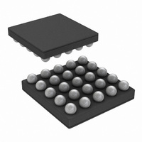
IC AMP AUDIO PWR 1.15W AB 25USMD
Manufacturer
National Semiconductor
Series
Boomer®r
Type
Class ABr
Datasheet
1.LM4846TLNOPB.pdf
(30 pages)
Specifications of LM4846TL/NOPB
Output Type
1-Channel (Mono) with Stereo Headphones
Max Output Power X Channels @ Load
1.15W x 1 @ 8 Ohm; 75mW x 2 @ 32 Ohm
Voltage - Supply
2.7 V ~ 5.5 V
Features
3D, Depop, I²C, Mute, Shutdown, SPI, Thermal Protection, Volume Control
Mounting Type
Surface Mount
Package / Case
25-MicroSMD
Operational Class
Class-AB
Audio Amplifier Function
Headphone/Speaker
Total Harmonic Distortion
0.5@8Ohm@500mW%
Single Supply Voltage (typ)
3/5V
Dual Supply Voltage (typ)
Not RequiredV
Supply Current (max)
11@3.3VmA
Power Supply Requirement
Single
Rail/rail I/o Type
No
Power Supply Rejection Ratio
88dB
Single Supply Voltage (min)
2.7V
Single Supply Voltage (max)
5.5V
Dual Supply Voltage (min)
Not RequiredV
Dual Supply Voltage (max)
Not RequiredV
Operating Temp Range
-40C to 85C
Operating Temperature Classification
Industrial
Mounting
Surface Mount
Pin Count
25
Package Type
uSMD
For Use With
LM4846TLEVAL - BOARD EVALUATION LM4846TL
Lead Free Status / RoHS Status
Lead free / RoHS Compliant
Other names
LM4846TLTR


Application Information
and reduced output power. Even with tightly regulated sup-
plies, trace resistance creates the same effects as poor
supply regulation. Therefore, making the power supply
traces as wide as possible helps maintain full output voltage
swing.
BRIDGE CONFIGURATION EXPLANATION
The LM4846 drives a load, such as a speaker, connected
between outputs, MONO+ and MONO-.
This results in both amplifiers producing signals identical in
magnitude, but 180˚ out of phase. Taking advantage of this
phase difference, a load is placed between MONO- and
MONO+ and driven differentially (commonly referred to as
”bridge mode”). This results in a differential or BTL gain of:
Bridge mode amplifiers are different from single-ended am-
plifiers that drive loads connected between a single amplifi-
er’s output and ground. For a given supply voltage, bridge
mode has a distinct advantage over the single-ended con-
figuration: its differential output doubles the voltage swing
across the load. Theoretically, this produces four times the
output power when compared to a single-ended amplifier
under the same conditions. This increase in attainable output
power assumes that the amplifier is not current limited and
that the output signal is not clipped.
Another advantage of the differential bridge output is no net
DC voltage across the load. This is accomplished by biasing
MONO- and MONO+ outputs at half-supply. This eliminates
the coupling capacitor that single supply, single-ended am-
plifiers require. Eliminating an output coupling capacitor in a
typical single-ended configuration forces a single-supply am-
plifier’s half-supply bias voltage across the load. This in-
creases internal IC power dissipation and may permanently
damage loads such as speakers.
POWER DISSIPATION
Power dissipation is a major concern when designing a
successful single-ended or bridged amplifier.
A direct consequence of the increased power delivered to
the load by a bridge amplifier is higher internal power dissi-
pation. The LM4846 has a pair of bridged-tied amplifiers
driving a handsfree speaker, MONO. The maximum internal
power dissipation operating in the bridge mode is twice that
of a single-ended amplifier. From Equation (8), assuming a
5V power supply and an 8Ω load, the maximum MONO
power dissipation is 634mW.
The LM4846 also has a pair of single-ended amplifiers driv-
ing stereo headphones, R
ternal power dissipation for R
equation (9) and (10). From Equations (9) and (10), assum-
ing a 5V power supply and a 32Ω load, the maximum power
dissipation for L
P
P
P
DMAX-ROUT
DMAX-LOUT
DMAX-SPKROUT
OUT
= (V
= (V
A
and R
DD
DD
= 4(V
VD
)
)
2
2
= 2(R
/ (2π
/ (2π
DD
OUT
OUT
)
2
2
2
f
and L
is 40mW, or 80mW total.
/ (2π
/ R
OUT
R
R
L
L
): Single-ended Mode (9)
i
): Single-ended Mode (10)
) = 2
2
and L
OUT
R
L
): Bridge Mode (8)
. The maximum in-
(Continued)
OUT
is given by
(7)
25
The maximum internal power dissipation of the LM4846
occurs when all 3 amplifiers pairs are simultaneously on; and
is given by Equation (11).
The maximum power dissipation point given by Equation
(11) must not exceed the power dissipation given by Equa-
tion (12):
The LM4846’s T
LM4846’s θ
T
dissipation supported by the IC packaging. Rearranging
Equation (12) and substituting P
sults in Equation (13). This equation gives the maximum
ambient temperature that still allows maximum stereo power
dissipation without violating the LM4846’s maximum junction
temperature.
For a typical application with a 5V power supply and an 8Ω
load, the maximum ambient temperature that allows maxi-
mum stereo power dissipation without exceeding the maxi-
mum junction temperature is approximately 104˚C for the
ITL package.
Equation (14) gives the maximum junction temperature T
MAX
maximum junction temperature by reducing the power sup-
ply voltage or increasing the load resistance. Further allow-
ance should be made for increased ambient temperatures.
The above examples assume that a device is a surface
mount part operating around the maximum power dissipation
point. Since internal power dissipation is a function of output
power, higher ambient temperatures are allowed as output
power or duty cycle decreases. If the result of Equation (11)
is greater than that of Equation (12), then decrease the
supply voltage, increase the load impedance, or reduce the
ambient temperature. If these measures are insufficient, a
heat sink can be added to reduce θ
created using additional copper area around the package,
with connections to the ground pin(s), supply pin and ampli-
fier output pins. External, solder attached SMT heatsinks
such as the Thermalloy 7106D can also improve power
dissipation. When adding a heat sink, the θ
θ
pedance, θ
θ
Typical Performance Characteristics curves for power dissi-
pation information at lower output power levels.
POWER SUPPLY BYPASSING
As with any power amplifier, proper supply bypassing is
critical for low noise performance and high power supply
rejection. Applications that employ a 5V regulator typically
use a 1µF in parallel with a 0.1µF filter capacitors to stabilize
the regulator’s output, reduce noise on the supply line, and
improve the supply’s transient response. However, their
presence does not eliminate the need for a local 1.1µF
tantalum bypass capacitance connected between the
JC
SA
A
, use Equation (12) to find the maximum internal power
, θ
. If the result violates the LM4846’s 150˚C, reduce the
is the sink-to-ambient thermal impedance). Refer to the
CS
P
, and θ
DMAX-SPKROUT
CS
JA
is 65˚C/W. At any given ambient temperature
T
T
is the case-to-sink thermal impedance, and
JMAX
SA
A
P
JMAX
DMAX
= T
. (θ
= P
JMAX
JC
P
= 150˚C. In the ITL package, the
+ P
= (T
DMAX-TOTAL
DMAX-TOTAL
is the junction-to-case thermal im-
- P
DMAX-LOUT
JMAX
DMAX-TOTAL
- T
DMAX-TOTAL
JA
=
A
θ
) / θ
. The heat sink can be
JA
+ P
+ T
JA
θ
DMAX-ROUT
JA
JA
A
for P
is the sum of
www.national.com
DMAX
’ re-
(12)
(13)
(14)
(11)
J -
Related parts for LM4846TL/NOPB
Image
Part Number
Description
Manufacturer
Datasheet
Request
R

Part Number:
Description:
National Semiconductor [8-Bit D/A Converter]
Manufacturer:
National Semiconductor
Datasheet:
Part Number:
Description:
National Semiconductor [Media Coprocessor]
Manufacturer:
National Semiconductor
Datasheet:
Part Number:
Description:
Digitally Controlled Tone and Volume Circuit with Stereo Audio Power Amplifier, Microphone Preamp Stage and National 3D Sound
Manufacturer:
National Semiconductor
Datasheet:
Part Number:
Description:
Digitally Controlled Tone and Volume Circuit with Stereo Audio Power Amplifier, Microphone Preamp Stage and National 3D Sound
Manufacturer:
National Semiconductor
Datasheet:
Part Number:
Description:
AC97 Rev 2 Codec with Sample Rate Conversion and National 3D Sound
Manufacturer:
National Semiconductor
Part Number:
Description:
Manufacturer:
National Semiconductor
Datasheet:
Part Number:
Description:
Manufacturer:
National Semiconductor
Datasheet:
Part Number:
Description:
General Purpose, Low Voltage, Low Power, Rail-to-Rail Output Operational Amplifiers
Manufacturer:
National Semiconductor
Datasheet:
Part Number:
Description:
8-bit 20 MSPS flash A/D converter.
Manufacturer:
National Semiconductor
Datasheet:
Part Number:
Description:
Low Noise Quad Operational Amplifier
Manufacturer:
National Semiconductor
Datasheet:
Part Number:
Description:
Quad Differential Line Receivers
Manufacturer:
National Semiconductor
Datasheet:
Part Number:
Description:
Quad High Speed Trapezoidal? Bus Transceiver
Manufacturer:
National Semiconductor
Datasheet:
Part Number:
Description:
Dual Line Receiver
Manufacturer:
National Semiconductor
Datasheet:
Part Number:
Description:
TTL to 10k ECL Level Translator with Latch
Manufacturer:
National Semiconductor
Datasheet: