LME49830TB/NOPB National Semiconductor, LME49830TB/NOPB Datasheet - Page 12
LME49830TB/NOPB
Manufacturer Part Number
LME49830TB/NOPB
Description
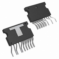
IC AMP AUDIO MONO HIFI TO247-15
Manufacturer
National Semiconductor
Type
Class ABr
Datasheet
1.LME49830TBNOPB.pdf
(20 pages)
Specifications of LME49830TB/NOPB
Output Type
1-Channel (Mono)
Voltage - Supply
±20 V ~ 100 V
Features
Mute, Thermal Protection
Mounting Type
Surface Mount
Package / Case
TO-247-15 (Bent and Staggered Leads)
For Use With
LME49830TBBD - BOARD EVALUATION FOR LME49830
Lead Free Status / RoHS Status
Lead free / RoHS Compliant
Max Output Power X Channels @ Load
-
Other names
*LME49830TB/NOPB
LME49830TB
LME49830TB-5
LME49830TB
LME49830TB
LME49830TB-5
LME49830TB
Available stocks
Company
Part Number
Manufacturer
Quantity
Price
Company:

Part Number:
LME49830TB/NOPB
Manufacturer:
AD
Quantity:
101
Company:
Part Number:
LME49830TB/NOPB
Manufacturer:
TI
Quantity:
201


www.national.com
Application Information
MUTE FUNCTION
The mute function of the LME49830 is controlled by the
amount of current that flows into the MUTE pin. If there is less
than 100μA of current flowing into the MUTE pin, the part will
be in mute mode. This can be achieved by shorting the MUTE
pin to ground. It is recommended to connect a capacitor C
(its value not less than 47μF) between the MUTE pin and
ground for reducing voltage fluctuation when switching be-
tween ‘play’ and ‘mute’ mode. If there is between 130μA and
2mA of current flowing into the MUTE pin, the part will be in
‘play’ mode. This can be done by connecting a power supply,
V
into the MUTE pin can be determined by the equation I
= (V
ample, if a 5V power supply is connected through a 27kΩ
resistor to the MUTE pin, then the mute current will be
154μA, at the center of the specified range. It is also possible
to use V
will have to be recalculated accordingly. It is not recommend-
ed to flow more than 2mA of current into the MUTE pin
because damage to the LME49830 may occur.
THERMAL PROTECTION
When the temperature on the die exceeds 150°C, the
LME49830 shuts down. It starts operating again when the die
temperature drops to about 145°C. When in thermal shut-
down, the current supply internal to the LME49830 will be cut-
off. There will be no signal generated to the output while in
thermal shutdown. After the die temperature decreases, the
LME49830 will power up again and resume normal operation.
If the fault conditions continue, thermal protection will be ac-
tivated and repeat the cycle preventing the LME49830 from
over heating.
Since the die temperature is directly dependent upon the heat
sink used, the heat sink should be chosen so that thermal
shutdown is not activated during normal operation. Using the
best heat sink possible within the cost and space constraints
of the system will improve the long-term reliability of any pow-
er semiconductor device, as discussed in the Determining the
Correct Heat Sink section. It is recommended to use a sepa-
rate heat sink from the output stage heat sink for the
LME49830. A heat sink may not be needed if the supply volt-
ages are low.
POWER DISSIPATION AND HEAT SINKING
When in “play” mode, the LME49830 draws a constant
amount of current, regardless of the input signal amplitude.
Consequently, the power dissipation is constant for a given
supply voltage and can be computed with the equation
P
P
the total supply voltage (the current varies slightly from this
value over the operating range).
DETERMINING THE CORRECT HEAT SINK
The choice of a heat sink for any power IC is made entirely to
keep the die temperature at a level such that the thermal pro-
tection circuitry is not activated under normal circumstances.
The thermal resistance from the die to the outside air, θ
(junction to ambient), is a combination of three thermal resis-
tances, θ
to ambient). The thermal resistance, θ
the LME49830TB is 4°C/W. Using Thermalloy Thermacote
thermal compound, the thermal resistance, θ
is about 0.2°C/W. Since convection heat flow (power dissi-
MUTE
DMAX
DMAX
MUTE
, to the MUTE pin through a resister, R
, approximate the current to be 20mA and multiply it by
= I
CC
JC
– V
CC
as the power supply for the MUTE pin, though R
(junction to case), θ
BE
* (V
) / (1kΩ +R
CC
– V
EE
M
) (W). For a quick calculation of
) (A), where V
CS
(case to sink), and θ
JC
(junction to case), of
BE
CS
≅
M
(case to sink),
. The current
0.7V. For ex-
SA
(sink
MUTE
JA
M
M
12
pation) is analogous to current flow, thermal resistance is
analogous to electrical resistance, and temperature drops are
analogous to voltage drops, the power dissipation out of the
LME49830 is equal to the following:
where T
ture and θ
Once the maximum package power dissipation has been cal-
culated, the maximum thermal resistance, θ
ambient) in °C/W for a heat sink can be calculated. This cal-
culation is made using equation 2 which is derived by solving
for θ
θ
Again it must be noted that the value of θ
the system designer's amplifier requirements. If the ambient
temperature that the audio amplifier is to be working under is
higher, then the thermal resistance for the heat sink, given all
other things are equal, will need to be smaller (better heat
sink).
PROPER SELECTION OF EXTERNAL COMPONENTS
Proper selection of external components is required to meet
the design targets of an application. The choice of external
component values that will affect gain and low frequency re-
sponse are discussed below.
The gain is set by resistors R
configuration shown in Figure 1. The gain is found by Equa-
tion 3 below:
For best noise performance, lower values of resistors are
used. For the LME49830 the gain should be set no lower than
26dB. Gain settings below 26dB may experience instability.
The combination of R
pass filter. The low frequency response is determined by
these two components. The -3dB point can be found from
Equation 4 shown below:
If an input coupling capacitor is used to block DC from the
inputs as shown in Figure 1, there will be another high-pass
filter created with the combination of C
a input coupling capacitor R
point on the amplifier's input terminal. The resulting -3dB fre-
quency response due to the combination of C
be found from Equation 5 shown below:
With large values of R
outputs when the inputs are left floating. Decreasing the value
of R
SA
IN
= [(T
SA
or not letting the inputs float will remove the oscillations.
in equation 1.
JMAX
JMAX
JA
P
= θ
DMAX
= 150°C, T
−T
f
IN
JC
AMB
A
f
i
= 1 / (2
= (T
V
+ θ
= 1 / (2
)−P
= 1 + R
CS
i
IN
JMAX
with C
DMAX
AMB
oscillations may be observed on the
+ θ
π
π
−T
R
f
R
SA
(θ
is the system ambient tempera-
/ R
IN
IN
i
i
AMB
C
JC
.
(see Figure 1) creates a high-
C
f
is needed to set the DC bias
i
i
) (Hz)
IN
and R
+θ
(V/V)
) / θ
) (Hz)
CS
JA
)] / P
IN
i
30005055
(W)
SA
for the non-inverting
and R
DMAX
is dependent upon
SA
IN
IN
, (heat sink to
(°C/W)
. When using
and R
IN
can
(1)
(2)
(3)
(4)
(5)
Related parts for LME49830TB/NOPB
Image
Part Number
Description
Manufacturer
Datasheet
Request
R

Part Number:
Description:
National Semiconductor [8-Bit D/A Converter]
Manufacturer:
National Semiconductor
Datasheet:
Part Number:
Description:
National Semiconductor [Media Coprocessor]
Manufacturer:
National Semiconductor
Datasheet:
Part Number:
Description:
Digitally Controlled Tone and Volume Circuit with Stereo Audio Power Amplifier, Microphone Preamp Stage and National 3D Sound
Manufacturer:
National Semiconductor
Datasheet:
Part Number:
Description:
Digitally Controlled Tone and Volume Circuit with Stereo Audio Power Amplifier, Microphone Preamp Stage and National 3D Sound
Manufacturer:
National Semiconductor
Datasheet:
Part Number:
Description:
AC97 Rev 2 Codec with Sample Rate Conversion and National 3D Sound
Manufacturer:
National Semiconductor
Part Number:
Description:
Manufacturer:
National Semiconductor
Datasheet:
Part Number:
Description:
Manufacturer:
National Semiconductor
Datasheet:
Part Number:
Description:
General Purpose, Low Voltage, Low Power, Rail-to-Rail Output Operational Amplifiers
Manufacturer:
National Semiconductor
Datasheet:
Part Number:
Description:
8-bit 20 MSPS flash A/D converter.
Manufacturer:
National Semiconductor
Datasheet:
Part Number:
Description:
Low Noise Quad Operational Amplifier
Manufacturer:
National Semiconductor
Datasheet:
Part Number:
Description:
Quad Differential Line Receivers
Manufacturer:
National Semiconductor
Datasheet:
Part Number:
Description:
Quad High Speed Trapezoidal? Bus Transceiver
Manufacturer:
National Semiconductor
Datasheet:
Part Number:
Description:
Dual Line Receiver
Manufacturer:
National Semiconductor
Datasheet:
Part Number:
Description:
TTL to 10k ECL Level Translator with Latch
Manufacturer:
National Semiconductor
Datasheet: