LM48311TL/NOPB National Semiconductor, LM48311TL/NOPB Datasheet - Page 10
LM48311TL/NOPB
Manufacturer Part Number
LM48311TL/NOPB
Description
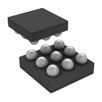
IC AMP AUDIO PWR 2.6W D 9USMD
Manufacturer
National Semiconductor
Series
Boomer®, PowerWise®r
Type
Class Dr
Datasheet
1.LM48311TLNOPB.pdf
(18 pages)
Specifications of LM48311TL/NOPB
Output Type
1-Channel (Mono)
Max Output Power X Channels @ Load
2.6W x 1 @ 4 Ohm
Voltage - Supply
2.4 V ~ 5.5 V
Features
Depop, Differential Inputs, E²S, Short-Circuit Protection, Shutdown
Mounting Type
Surface Mount
Package / Case
9-MicroSMD
Lead Free Status / RoHS Status
Lead free / RoHS Compliant
Other names
LM48311TL
LM48311TL
LM48311TLTR
LM48311TL
LM48311TLTR


www.national.com
Application Information
GENERAL AMPLIFIER FUNCTION
The LM48311 mono Class D audio power amplifier features
a filterless modulation scheme that reduces external compo-
nent count, conserving board space and reducing system
cost. The outputs of the device transition from V
with a 300kHz switching frequency. With no signal applied,
the outputs (V
in phase, causing the two outputs to cancel. This cancellation
results in no net voltage across the speaker, thus there is no
current to the load in the idle state.
With the input signal applied, the duty cycle (pulse width) of
the LM48311 outputs changes. For increasing output voltage,
the duty cycle of V
V
verse occurs. The difference between the two pulse widths
yields the differential output voltage.
ENHANCED EMISSIONS SUPPRESSION SYSTEM (E
The LM48311 features National’s patent-pending E
that reduces EMI, while maintaining high quality audio repro-
duction and efficiency. The E
trum and advanced edge rate control (ERC). The LM48311
ERC greatly reduces the high frequency components of the
output square waves by controlling the output rise and fall
times, slowing the transitions to reduce RF emissions, while
maximizing THD+N and efficiency performance. The overall
result of the E
passes FCC Class B radiated emissions standards with 20in
of twisted pair cable, with excellent 0.03% THD+N and high
88% efficiency.
SPREAD SPECTRUM
The spread spectrum modulation reduces the need for output
filters, ferrite beads or chokes. The switching frequency varies
randomly by 30% about a 300kHz center frequency, reducing
the wideband spectral contend, improving EMI emissions ra-
diated by the speaker and associated cables and traces.
Where a fixed frequency class D exhibits large amounts of
spectral energy at multiples of the switching frequency, the
spread spectrum architecture of the LM48311 spreads that
energy over a larger bandwidth (See Typical Performance
Characteristics). The cycle-to-cycle variation of the switching
period does not affect the audio reproduction, efficiency, or
PSRR.
DIFFERENTIAL AMPLIFIER EXPLANATION
As logic supplies continue to shrink, system designers are in-
creasingly turning to differential analog signal handling to
preserve signal to noise ratios with restricted voltage signs.
The LM48311 features a fully differential speaker amplifier. A
differential amplifier amplifies the difference between the two
input signals. Traditional audio power amplifiers have typical-
ly offered only single-ended inputs resulting in a 6dB reduc-
tion of SNR relative to differential inputs. The LM48311 also
offers the possibility of DC input coupling which eliminates the
input coupling capacitors. A major benefit of the fully differ-
ential amplifier is the improved common mode rejection ratio
(CMRR) over single ended input amplifiers. The increased
CMRR of the differential amplifier reduces sensitivity to
ground offset related noise injection, especially
POWER DISSIPATION AND EFFICIENCY
The major benefit of a Class D amplifier is increased efficiency
versus a Class AB. The efficiency of the LM48311 is attributed
to the region of operation of the transistors in the output stage.
OUTB
decreases. For decreasing output voltages, the con-
OUTA
2
S system is a filterless Class D amplifier that
and V
OUTA
OUTB
increases, while the duty cycle of
2
S system features spread spec-
) switch with a 50% duty cycle,
DD
2
S system
to GND
2
S)
10
The Class D output stage acts as current steering switches,
consuming negligible amounts of power compared to their
Class AB counterparts. Most of the power loss associated
with the output stage is due to the IR loss of the MOSFET on-
resistance, along with switching losses due to gate charge.
SHUTDOWN FUNCTION
The LM48311 features a low current shutdown mode. Set
SD = GND to disable the amplifier and reduce supply current
to 0.01µA.
Switch SD between GND and V
sumption is shutdown. The LM48311 may be disabled with
shutdown voltages in between GND and V
will be greater than the typical 0.1µA value. Increased THD
+N may also be observed when a voltage of less than V
applied to SD.
The LM48311 shutdown input has and internal pulldown re-
sistor. The purpose of this resistor is to eliminate any unwant-
ed state changes when SD is floating. To minimize shutdown
current, SD should be driven to GND or left floating. If SD is
not driven to GND or floating, an increase in shutdown supply
current will be noticed.
AUDIO AMPLIFIER POWER SUPPLY BYPASSING/
FILTERING
Proper power supply bypassing is critical for low noise per-
formance and high PSRR. Place the supply bypass capaci-
tors as close to the device as possible. Typical applications
employ a voltage regulator with 10µF and 0.1µF bypass ca-
pacitors that increase supply stability. These capacitors do
not eliminate the need for bypassing of the LM48311 supply
pins. A 1µF capacitor is recommended.
AUDIO AMPLIFIER INPUT CAPACITOR SELECTION
Input capacitors may be required for some applications, or
when the audio source is single-ended. Input capacitors block
the DC component of the audio signal, eliminating any conflict
between the DC component of the audio source and the bias
voltage of the LM48311. The input capacitors create a high-
pass filter with the input resistors R
high pass filter is found using Equation (1) below.
Where R
trical Characteristics table.
The input capacitors can also be used to remove low fre-
quency content from the audio signal. Small speakers cannot
reproduce, and may even be damaged by low frequencies.
High pass filtering the audio signal helps protect the speakers.
When the LM48311 is using a single-ended source, power
supply noise on the ground is seen as an input signal. Setting
the high-pass filter point above the power supply noise fre-
quencies, 217Hz in a GSM phone, for example, filters out the
noise such that it is not amplified and heard on the output.
Capacitors with a tolerance of 10% or better are recommend-
ed for impedance matching and improved CMRR and PSRR.
AUDIO AMPLIFIER GAIN
The gain of the LM48311 is internally set to 6dB. The gain can
be reduced by adding additional input resistance (Figure 6).
In this configuration, the gain of the device is given by:
IN
is the value of the input resistor given in the Elec-
f = 1 / 2
π
R
DD
IN
C
for minimum current con-
IN
IN
. The -3dB point of the
DD
, the idle current
DD
is
Related parts for LM48311TL/NOPB
Image
Part Number
Description
Manufacturer
Datasheet
Request
R

Part Number:
Description:
Multimedia Computer Audio Chip
Manufacturer:
National Semiconductor
Part Number:
Description:
National Semiconductor [8-Bit D/A Converter]
Manufacturer:
National Semiconductor
Datasheet:
Part Number:
Description:
National Semiconductor [Media Coprocessor]
Manufacturer:
National Semiconductor
Datasheet:
Part Number:
Description:
Digitally Controlled Tone and Volume Circuit with Stereo Audio Power Amplifier, Microphone Preamp Stage and National 3D Sound
Manufacturer:
National Semiconductor
Datasheet:
Part Number:
Description:
Digitally Controlled Tone and Volume Circuit with Stereo Audio Power Amplifier, Microphone Preamp Stage and National 3D Sound
Manufacturer:
National Semiconductor
Datasheet:
Part Number:
Description:
AC97 Rev 2 Codec with Sample Rate Conversion and National 3D Sound
Manufacturer:
National Semiconductor
Part Number:
Description:
Manufacturer:
National Semiconductor
Datasheet:
Part Number:
Description:
Manufacturer:
National Semiconductor
Datasheet:
Part Number:
Description:
General Purpose, Low Voltage, Low Power, Rail-to-Rail Output Operational Amplifiers
Manufacturer:
National Semiconductor
Datasheet:
Part Number:
Description:
8-bit 20 MSPS flash A/D converter.
Manufacturer:
National Semiconductor
Datasheet:
Part Number:
Description:
Low Noise Quad Operational Amplifier
Manufacturer:
National Semiconductor
Datasheet:
Part Number:
Description:
Quad Differential Line Receivers
Manufacturer:
National Semiconductor
Datasheet:
Part Number:
Description:
Quad High Speed Trapezoidal? Bus Transceiver
Manufacturer:
National Semiconductor
Datasheet:
Part Number:
Description:
Dual Line Receiver
Manufacturer:
National Semiconductor
Datasheet: