1-1734081-3 TE Connectivity, 1-1734081-3 Datasheet - Page 3
1-1734081-3
Manufacturer Part Number
1-1734081-3
Description
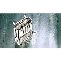
USB Connectors USB 2.0 Female USB Type A Connector
Manufacturer
TE Connectivity
Series
Ar
Specifications of 1-1734081-3
Product
USB Type A Connectors
Standard
USB 2.0
Number Of Ports
1
Contact Plating
Gold
Contact Material
Gold
Gender
Female
Mounting Style
Snap On
Termination Style
Solder Tail
Connector Type
USB Type A Receptacle with top mount
Number Of Positions / Contacts
4
Size
Standard
Orientation
Right Angle
Mount Location
Top
Termination Method
Solder
Tail Length (mm [in])
2.25 [0.089]
Locking Feature
Without
Led
Without
Panel Ground
Without
Pcb Mount Retention Type
Straight Leg
Shell Plating
Nickel over Copper
Assembly Process Feature
Without Pick and Place Cover
Locating Post(s)
Without
Number Of Positions
4
Contact Termination Type
Through Hole
Contact Plating, Mating Area, Material
Gold
Contact Plating, Mating Area, Thickness (µm [?in])
0.762 [30]
Housing Color
Black
Industry Standard
USB 2.0
Rohs/elv Compliance
RoHS compliant, ELV compliant
Lead Free Solder Processes
Wave solder capable to 240°C, Wave solder capable to 260°C, Wave solder capable to 265°C
Rohs/elv Compliance History
Always was RoHS compliant
Usb-if Test Id Number (tid)
Not Submitted For Testing
Applies To
Printed Circuit Board
Pcb Thickness, Recommended (mm [in])
1.60 [0.063]
Packaging Method
Tape & Reel
Lead Free Status / Rohs Status
Details


Rev
12
13 Solder ability
12
12
12
12
12
15 Thermal Shock
16
17
18 Salt Spray
Contact Retention
Force
Resistance to Wave
Soldering Heat
Resistance to Wave
Soldering Heat
Resistance to Reflow
Soldering Heat
Resistance to Reflow
Soldering Heat
Resistance to Reflow
Soldering Heat
Humidity-Temperature
Cycle
Temperature Life
(Heat Aging)
B
TEST ITEM
1000 gf Min.
The inspected area of each
lead must have 95% solder
coverage minimum.
No physical damage shall
occur.
No physical damage shall
occur.
No physical damage shall
occur.
No physical damage shall
occur.
No physical damage shall
occur.
See Note
See Note
See Note
No detrimental corrosion
allowed in contact area and
base metal exposed.
ENVIRONMENTAL REQUIREMENTS
MECHANICAL REQUIREMENT
REQUIREMENT
Figure 1(End)
Measure the contact retention force with
Steam Aging Preconditioning:
1. Intended for nontin and nontin-alloy
lead finishes for 93+3/-5℃、1hrs.
2. Intended for tin and tin-alloy lead
finishes for 93+3/-5℃、8hrs.
<JESD22-B102D, Condition C>
Solder pot temperature: 245±5℃, 5sec
Solder Temp.:240±5℃, 10±0.5sec.
TE spec. 109-202, Condition A
Solder Temp.:265±5℃, 10±0.5sec.
TE spec. 109-202, Condition B
Pre Heat:100~150℃, 60 sec Max.
Heat:210℃ Min., 30 sec Max.
Peak Temp.:240℃ Max., 10±0.5sec.
Pre-soak condition, 85 ℃ /85 ﹪ RH for
168 hours.
Pre Heat:150~180℃, 90±30sec.
Heat:230℃ Min., 30±10sec.
Peak Temp.:245+0/-5℃, 10~30sec.
Duration:3 cycles
TE spec. 109-201, Condition A
Pre-soak condition, 85 ℃ /85 ﹪ RH for
168 hours.
Pre Heat:150~180℃, 90±30sec.
Heat:230℃ Min., 30±10sec.
Peak Temp.:260+0/-5℃, 20~40sec.
Duration:3 cycles
TE spec. 109-201, Condition B
Mated Connector
-55+/-3 (30 minutes), +85+/
minutes)
Perform this a cycle, repeat 10 cycles
EIA-364-32C
Mated Connector
25~65
(seven complete cycles) EIA-364-31B.
Mated Connector
85
Subject mated connectors to 35+/-2 ℃
and 5+/-1% salt condition for 48hours.
After test, rinse the sample with water
and recondition the room temperature
for 1 hour. EIA-364-26B.
Tensile strength tester.
℃
, 250 hours, EIA
℃
℃
, 90~95% RH,
PROCEDURE
-364-17B.
168 Hours
108-57505
-2 (30
℃
3 of 5