LM4934RL/NOPB National Semiconductor, LM4934RL/NOPB Datasheet - Page 24
LM4934RL/NOPB
Manufacturer Part Number
LM4934RL/NOPB
Description
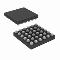
IC AUDIO SUBSYSTEM 1.2W 42USMDXT
Manufacturer
National Semiconductor
Series
Boomer®r
Type
Class ABr
Datasheet
1.LM4934RLNOPB.pdf
(39 pages)
Specifications of LM4934RL/NOPB
Output Type
2-Channel (Stereo) with Mono and Stereo Headphones
Max Output Power X Channels @ Load
1.2W x 2 @ 8 Ohm; 80mW x 2 @ 32 Ohm
Voltage - Supply
2.7 V ~ 5.5 V
Features
3D, Depop, I²C, I²S, Mute, Shutdown, SPI, Volume Control
Mounting Type
Surface Mount
Package / Case
42-MicroSMDxt
Lead Free Status / RoHS Status
Lead free / RoHS Compliant
Other names
LM4934RL
LM4934RLTR
LM4934RLTR


www.national.com
Common Clock Settings for the DAC
Methods for producing these clock frequencies are described in the PLL section.
The R divider can be used when the master clock is exactly 12.00 MHz in order to generate different sample rates. The Table
below shows different sample rates supported from 12.00MHz by using only the R divider and disabling the PLL. In this way we
can save power and the clock jitter will be low.
The R divider can also be used along with the P divider in order to create the clock needed to support low sample rates.
DAC Setup Register
This register is used to configure the basic operation of the stereo DAC.
DAC_SETUP (0Eh)
R_DIV
11
9
7
5
4
3
2
0
Fs (kHz)
176.4
44.1
44.1
88.2
192
Bits
48
48
96
1:0
2
3
4
5
6
Divide Value
2.5
1.5
6
5
4
3
2
1
DITHER_OFF
ALWAYS_ON
CUST_COMP
DAC_MODE
DAC Oversampling Ratio
MUTE_R
Register
MUTE_L
DITHER
DAC Clock Generator Input Frequency
(Set = logic 1, Clear = logic 0)
125
128
125
128
64
64
32
32
If set the DAC frequency response can be programmed manually via a 5 tap FIR
DAC_MODE
“compensation” filter. This can be used to enhance the frequency response of
The DAC used in the LM4934 can operate in one of 4 oversampling modes.
small loudspeakers or provide a crude tone control. The compensation
00
01
10
11
Mutes the right DAC channel on the next zero crossing.
Mutes the left DAC channel on the next zero crossing.
2.4
4.8
Coefficients can be set by using registers 10h to 15h.
12
2
3
4
6
8
If set the dither in DAC is enabled all the time.
Oversampling
Rate
125
128
64
32
24
Required CLock at DAC Clock Generator Input (MHz)
(Continued)
The modes are described as follows:
If set the dither in DAC is disabled.
<
MHz
Description
Typical FS
48KHz
44.1KHz
48KHz
96KHz
192KHz
>
22.5792
11.2896
11.2896
12.288
12.288
24.576
11.025
Sample Rate Supported
12
Clock Required
12.000MHz (USB
Mode)
11.2896MHz
12.288MHz
12.288MHz
24.576MHz
19.2
9.6
12
16
24
32
48
8
<
KHz
>
Related parts for LM4934RL/NOPB
Image
Part Number
Description
Manufacturer
Datasheet
Request
R

Part Number:
Description:
National Semiconductor [8-Bit D/A Converter]
Manufacturer:
National Semiconductor
Datasheet:
Part Number:
Description:
National Semiconductor [Media Coprocessor]
Manufacturer:
National Semiconductor
Datasheet:
Part Number:
Description:
Digitally Controlled Tone and Volume Circuit with Stereo Audio Power Amplifier, Microphone Preamp Stage and National 3D Sound
Manufacturer:
National Semiconductor
Datasheet:
Part Number:
Description:
Digitally Controlled Tone and Volume Circuit with Stereo Audio Power Amplifier, Microphone Preamp Stage and National 3D Sound
Manufacturer:
National Semiconductor
Datasheet:
Part Number:
Description:
AC97 Rev 2 Codec with Sample Rate Conversion and National 3D Sound
Manufacturer:
National Semiconductor
Part Number:
Description:
Manufacturer:
National Semiconductor
Datasheet:
Part Number:
Description:
Manufacturer:
National Semiconductor
Datasheet:
Part Number:
Description:
General Purpose, Low Voltage, Low Power, Rail-to-Rail Output Operational Amplifiers
Manufacturer:
National Semiconductor
Datasheet:
Part Number:
Description:
8-bit 20 MSPS flash A/D converter.
Manufacturer:
National Semiconductor
Datasheet:
Part Number:
Description:
Low Noise Quad Operational Amplifier
Manufacturer:
National Semiconductor
Datasheet:
Part Number:
Description:
Quad Differential Line Receivers
Manufacturer:
National Semiconductor
Datasheet:
Part Number:
Description:
Quad High Speed Trapezoidal? Bus Transceiver
Manufacturer:
National Semiconductor
Datasheet:
Part Number:
Description:
Dual Line Receiver
Manufacturer:
National Semiconductor
Datasheet:
Part Number:
Description:
TTL to 10k ECL Level Translator with Latch
Manufacturer:
National Semiconductor
Datasheet: