LM4673TM/NOPB National Semiconductor, LM4673TM/NOPB Datasheet - Page 12
LM4673TM/NOPB
Manufacturer Part Number
LM4673TM/NOPB
Description
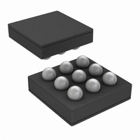
IC AMP AUDIO PWR 2.65W D 9USMD
Manufacturer
National Semiconductor
Series
Boomer®, PowerWise®r
Type
Class Dr
Datasheet
1.LM4673SDNOPB.pdf
(24 pages)
Specifications of LM4673TM/NOPB
Output Type
1-Channel (Mono)
Max Output Power X Channels @ Load
2.65W x 1 @ 4 Ohm
Voltage - Supply
2.4 V ~ 5.5 V
Features
Depop, Differential Inputs, PWM, Short-Circuit and Thermal Protection, Shutdown
Mounting Type
Surface Mount
Package / Case
9-MicroSMD
For Use With
LM4673TMBD - BOARD EVALUATION LM4673TM
Lead Free Status / RoHS Status
Lead free / RoHS Compliant
Other names
LM4673TM
LM4673TMTR
LM4673TMTR


www.national.com
due to the internal shutdown resistor can be found by Equa-
tion (1) below.
With only a 0.5V difference, an additional 1.7µA of current will
be drawn while in the shutdown state.
PROPER SELECTION OF EXTERNAL COMPONENTS
The gain of the LM4673 is set by the external resistors, Ri in
Figure 1, The Gain is given by Equation (2) below. Best THD
+N performance is achieved with a gain of 2V/V (6dB).
It is recommended that resistors with 1% tolerance or better
be used to set the gain of the LM4673. The Ri resistors should
be placed close to the input pins of the LM4673. Keeping the
input traces close to each other and of the same length in a
high noise environment will aid in noise rejection due to the
good CMRR of the LM4673. Noise coupled onto input traces
which are physically close to each other will be common mode
and easily rejected by the LM4673.
Input capacitors may be needed for some applications or
when the source is single-ended (see Figures 3, 5). Input ca-
pacitors are needed to block any DC voltage at the source so
that the DC voltage seen between the input terminals of the
LM4673 is 0V. Input capacitors create a high-pass filter with
the input resistors, R
is found using Equation (3) below.
The input capacitors may also be used to remove low audio
frequencies. Small speakers cannot reproduce low bass fre-
quencies so filtering may be desired . When the LM4673 is
using a single-ended source, power supply noise on the
ground is seen as an input signal by the +IN input pin that is
capacitor coupled to ground (See Figures 5 – 7). Setting the
high-pass filter point above the power supply noise frequen-
cies, 217Hz in a GSM phone, for example, will filter out this
noise so it is not amplified and heard on the output. Capacitors
with a tolerance of 10% or better are recommended for
impedance matching.
DIFFERENTIAL CIRCUIT CONFIGURATIONS
The LM4673 can be used in many different circuit configura-
tions. The simplest and best performing is the DC coupled,
A
V
f
(V
C
= 2 * 150 kΩ / R
= 1 / (2πR
SD
i
. The –3dB point of the high-pass filter
- GND) / 300kΩ
i
C
i
) (Hz)
i
(V/V)
(1)
(2)
(3)
12
differential input configuration shown in Figure 2. Equation (2)
above is used to determine the value of the R
desired gain.
Input capacitors can be used in a differential configuration as
shown in Figure 3. Equation (3) above is used to determine
the value of the C
sponse due to the high-pass filter created by C
Equation (2) above is used to determine the value of the R
resistors for a desired gain.
The LM4673 can be used to amplify more than one audio
source. Figure 4 shows a dual differential input configuration.
The gain for each input can be independently set for maxi-
mum design flexibility using the R
Equation (2). Input capacitors can be used with one or more
sources as well to have different frequency responses de-
pending on the source or if a DC voltage needs to be blocked
from a source.
SINGLE-ENDED CIRCUIT CONFIGURATIONS
The LM4673 can also be used with single-ended sources but
input capacitors will be needed to block any DC at the input
terminals. Figure 5 shows the typical single-ended application
configuration. The equations for Gain, Equation (2), and fre-
quency response, Equation (3), hold for the single-ended
configuration as shown in Figure 5.
When using more than one single-ended source as shown in
Figure 6, the impedance seen from each input terminal should
be equal. To find the correct values for C
to the +IN input pin the equivalent impedance of all the single-
ended sources are calculated. The single-ended sources are
in parallel to each other. The equivalent capacitor and resis-
tor, C
nation of all C
(5) below are for any number of single-ended sources.
The LM4673 may also use a combination of single-ended and
differential sources. A typical application with one single-end-
ed source and one differential source is shown in Figure 7.
Using the principle of superposition, the external component
values can be determined with the above equations corre-
sponding to the configuration.
i3
and R
R
i3
= 1 / (1/R
i
values and then all R
i3
C
, are found by calculating the parallel combi-
i3
= C
i
capacitors for a desired frequency re-
i1
i1
+ C
+ 1/R
i2
+ C
i2
+ 1/R
in
i
resistors for each input and
i
... (F)
values. Equations (4) and
in
...) (Ω)
i3
and R
i
resistors for a
i3
connected
i
and R
(4)
(5)
i
.
i
Related parts for LM4673TM/NOPB
Image
Part Number
Description
Manufacturer
Datasheet
Request
R

Part Number:
Description:
AUDIO AMP, MONO CLASS D, POWERWISE
Manufacturer:
National Semiconductor
Datasheet:

Part Number:
Description:
National Semiconductor [8-Bit D/A Converter]
Manufacturer:
National Semiconductor
Datasheet:
Part Number:
Description:
National Semiconductor [Media Coprocessor]
Manufacturer:
National Semiconductor
Datasheet:
Part Number:
Description:
Digitally Controlled Tone and Volume Circuit with Stereo Audio Power Amplifier, Microphone Preamp Stage and National 3D Sound
Manufacturer:
National Semiconductor
Datasheet:
Part Number:
Description:
Digitally Controlled Tone and Volume Circuit with Stereo Audio Power Amplifier, Microphone Preamp Stage and National 3D Sound
Manufacturer:
National Semiconductor
Datasheet:
Part Number:
Description:
AC97 Rev 2 Codec with Sample Rate Conversion and National 3D Sound
Manufacturer:
National Semiconductor
Part Number:
Description:
Manufacturer:
National Semiconductor
Datasheet:
Part Number:
Description:
Manufacturer:
National Semiconductor
Datasheet:
Part Number:
Description:
General Purpose, Low Voltage, Low Power, Rail-to-Rail Output Operational Amplifiers
Manufacturer:
National Semiconductor
Datasheet:
Part Number:
Description:
8-bit 20 MSPS flash A/D converter.
Manufacturer:
National Semiconductor
Datasheet:
Part Number:
Description:
Low Noise Quad Operational Amplifier
Manufacturer:
National Semiconductor
Datasheet:
Part Number:
Description:
Quad Differential Line Receivers
Manufacturer:
National Semiconductor
Datasheet:
Part Number:
Description:
Quad High Speed Trapezoidal? Bus Transceiver
Manufacturer:
National Semiconductor
Datasheet:
Part Number:
Description:
Dual Line Receiver
Manufacturer:
National Semiconductor
Datasheet: