LMV1032URX-25/NOPB National Semiconductor, LMV1032URX-25/NOPB Datasheet - Page 3
LMV1032URX-25/NOPB
Manufacturer Part Number
LMV1032URX-25/NOPB
Description
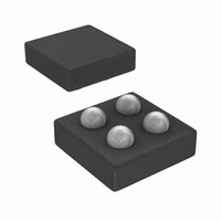
IC AMP AUDIO MONO AB MIC 4USMD
Manufacturer
National Semiconductor
Type
Class ABr
Datasheet
1.LMV1032UPX-06NOPB.pdf
(12 pages)
Specifications of LMV1032URX-25/NOPB
Output Type
1-Channel (Mono)
Voltage - Supply
1.7 V ~ 5 V
Features
Microphone
Mounting Type
Surface Mount
Package / Case
4-MicroSMD
Operational Class
Class-AB
Audio Amplifier Output Configuration
1-Channel Mono
Audio Amplifier Function
Microphone
Total Harmonic Distortion
0.35%
Single Supply Voltage (typ)
3V
Dual Supply Voltage (typ)
Not RequiredV
Supply Current (max)
0.085@5VmA
Power Supply Requirement
Single
Rail/rail I/o Type
No
Power Supply Rejection Ratio
65dB
Single Supply Voltage (min)
1.7V
Single Supply Voltage (max)
5V
Dual Supply Voltage (min)
Not RequiredV
Dual Supply Voltage (max)
Not RequiredV
Operating Temp Range
-40C to 85C
Operating Temperature Classification
Industrial
Mounting
Surface Mount
Pin Count
4
Package Type
uSMD
Lead Free Status / RoHS Status
Lead free / RoHS Compliant
Max Output Power X Channels @ Load
-
Lead Free Status / Rohs Status
Compliant
Other names
LMV1032URX-25


THD
C
Z
A
Symbol
IN
1.7V and 5V Electrical Characteristics
V
IN
Unless otherwise specified, all limits guaranteed for T
ture extremes.
Note 1: Absolute Maximum Ratings indicate limits beyond which damage to the device may occur. Operating Ratings indicate conditions for which the device is
intended to be functional, but specific performance is not guaranteed. For guaranteed specifications and the test conditions, see the Electrical Characteristics.
Note 2: The Human Body Model (HBM) is 1.5 kΩ in series with 100 pF. The Machine Model is 0Ω in series with 200 pF.
Note 3: Electrical Table values apply only for factory testing conditions at the temperature indicated. Factory testing conditions result in very limited self-heating of
the device such that T
Note 4: All limits are guaranteed by design or statistical analysis.
Note 5: Typical values represent the most likely parametric norm.
Note 6: The maximum power dissipation is a function of T
(T
J(MAX)
- T
A
Total Harmonic Distortion
Input Capacitance
Input Impedance
Gain
)/θ
JA
. All numbers apply for packages soldered directly onto a PC board.
J
= T
Parameter
A
. No guarantee of parametric performance is indicated in the electrical tables under conditions of internal self-heating where T
f = 1 kHz
V
f = 1 kHz
V
IN
IN
J(MAX)
= 18 mV
= 18 mV
, θ
J
JA
= 25˚C and V
and T
PP
PP
Conditions
A
. The maximum allowable power dissipation at any ambient temperature is P
3
(Note 3) (Continued)
DD
LMV1032-06
LMV1032-15
LMV1032-25
LMV1032-06
LMV1032-15
LMV1032-25
= 1.7V and 5V. Boldface limits apply at the tempera-
(Note 4)
14.8
24.8
Min
5.5
4.5
14
24
(Note 5)
>
0.11
0.13
0.35
15.4
25.5
Typ
6.2
100
2
(Note 4)
Max
26.2
6.7
7.7
16
17
27
www.national.com
J
Units
MΩ
>
pF
dB
%
D
T
A
=
.
Related parts for LMV1032URX-25/NOPB
Image
Part Number
Description
Manufacturer
Datasheet
Request
R

Part Number:
Description:
IC AMP AUDIO MONO AB MIC 4USMD
Manufacturer:
National Semiconductor
Datasheet:

Part Number:
Description:
Manufacturer:
National Semiconductor
Datasheet:

Part Number:
Description:
Amplifiers For 3-wire Analog Electret Microphones
Manufacturer:
National Semiconductor Corporation
Datasheet:
Part Number:
Description:
National Semiconductor [8-Bit D/A Converter]
Manufacturer:
National Semiconductor
Datasheet:
Part Number:
Description:
National Semiconductor [Media Coprocessor]
Manufacturer:
National Semiconductor
Datasheet:
Part Number:
Description:
Digitally Controlled Tone and Volume Circuit with Stereo Audio Power Amplifier, Microphone Preamp Stage and National 3D Sound
Manufacturer:
National Semiconductor
Datasheet:
Part Number:
Description:
Digitally Controlled Tone and Volume Circuit with Stereo Audio Power Amplifier, Microphone Preamp Stage and National 3D Sound
Manufacturer:
National Semiconductor
Datasheet:
Part Number:
Description:
AC97 Rev 2 Codec with Sample Rate Conversion and National 3D Sound
Manufacturer:
National Semiconductor
Part Number:
Description:
Manufacturer:
National Semiconductor
Datasheet:
Part Number:
Description:
Manufacturer:
National Semiconductor
Datasheet:
Part Number:
Description:
General Purpose, Low Voltage, Low Power, Rail-to-Rail Output Operational Amplifiers
Manufacturer:
National Semiconductor
Datasheet:
Part Number:
Description:
8-bit 20 MSPS flash A/D converter.
Manufacturer:
National Semiconductor
Datasheet:
Part Number:
Description:
Low Noise Quad Operational Amplifier
Manufacturer:
National Semiconductor
Datasheet:
Part Number:
Description:
Quad Differential Line Receivers
Manufacturer:
National Semiconductor
Datasheet: