MAX9711ETC+ Maxim Integrated Products, MAX9711ETC+ Datasheet - Page 9

MAX9711ETC+
Manufacturer Part Number
MAX9711ETC+
Description
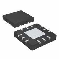
IC AMP AUDIO PWR 3W MONO 12TQFN
Manufacturer
Maxim Integrated Products
Type
Class ABr
Datasheet
1.MAX9711ETCT.pdf
(13 pages)
Specifications of MAX9711ETC+
Output Type
1-Channel (Mono)
Max Output Power X Channels @ Load
3W x 1 @ 3 Ohm
Voltage - Supply
4.5 V ~ 5.5 V
Features
Depop, Mute, Shutdown, Thermal Protection
Mounting Type
Surface Mount
Package / Case
12-TQFN Exposed Pad
Lead Free Status / RoHS Status
Lead free / RoHS Compliant
Figure 2. MAX9711 Piezoelectric Speaker Driver THD+N vs.
Frequency
The capacitive nature of the piezoelectric speaker may
cause the MAX9711 to become unstable. A simple induc-
tor/resistor network in series with the speaker isolates the
speaker capacitance from the driver and ensures that the
device output sees a resistive load of about 10Ω at high
frequency, thereby maintaining stability (Figure 3).
Good PC board layout is essential for optimizing perfor-
mance. Use large traces for the power-supply inputs and
amplifier outputs to minimize losses due to parasitic
trace resistance and route heat away from the device.
Good grounding improves audio performance,
minimizes crosstalk between channels, and prevents any
digital switching noise from coupling into the audio
signal.
The MAX9710/MAX9711 thin QFN package features an
exposed thermal pad on the underside. This pad low-
ers the thermal resistance of the package by providing
a direct-heat conduction path from the die to the print-
ed circuit board. Connect the exposed pad to the
ground plane using multiple vias, if required. For opti-
mum performance, connect to the ground planes as
shown in Figure 4.
3W Mono/Stereo BTL Audio Power Amplifiers
0.001
0.01
0.1
10
1
TOTAL HARMONIC DISTORTI0N PLUS NOISE
0.01
_______________________________________________________________________________________
0.1
vs. FREQUENCY
FREQUENCY (Hz)
Layout and Grounding
1
V
10
OUT
= 8V
P-P
100
Figure 3. Isolation Network for Driving a Piezoelectric Speaker
Figure 4. MAX9710 Audio Ground Connection
AUDIO
INPUT
5V
1μF
AUDIO SIGNAL
PGND
GND
15kΩ
PV
DD
2
MAX9710
IN
with Shutdown
V
15kΩ
DD
MAX9711
FOR OPTIMUM PERFORMANCE,
AUDIO GND SHOULD HAVE A
STAR CONNECTION TO THE HIGH
CURRENT, AMPLIFIER PGND AT
A SINGLE POINT, PIN 6.
OUT+
OUT-
12
4
*
SPEAKER.
PIEZOELECTRIC
100μH
10Ω
*
9


