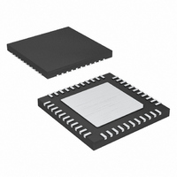
MAX9744ETH+T Maxim Integrated Products, MAX9744ETH+T Datasheet - Page 21

MAX9744ETH+T
Manufacturer Part Number
MAX9744ETH+T
Description
IC AMP AUDIO PWR 22.5W D 44TQFN
Manufacturer
Maxim Integrated Products
Type
Class Dr
Datasheet
1.MAX9744ETH.pdf
(28 pages)
Specifications of MAX9744ETH+T
Output Type
2-Channel (Stereo)
Max Output Power X Channels @ Load
22.5W x 2 @ 4 Ohm
Voltage - Supply
4.5 V ~ 14 V
Features
Depop, Mute, Short-Circuit and Thermal Protection, Shutdown, Volume Control
Mounting Type
Surface Mount
Package / Case
44-TQFN Exposed Pad
Lead Free Status / RoHS Status
Lead free / RoHS Compliant
The MAX9744 meets common EMC radiation limits with-
out a filter when the speaker leads are less than approxi-
mately 10cm. Using lengths beyond 10cm is possible
verifying against the appropriate EMC standard.
For longer speaker wire lengths, up to approximately
1m, use a simple ferrite bead and capacitor filter to
meet EMC limits. Select a ferrite bead with 100Ω to
600Ω impedance, and rated for at least 3A. The capaci-
tor value varies based on the ferrite bead chosen and
the actual speaker lead length. Select the capacitor
value based on EMC performance. See Figure 7 for the
correct connections of these components.
When evaluating the device without a filter or a ferrite
bead filter, include a series inductor (68µH for 8Ω load
and 33µH for 4Ω load) to model the actual loudspeak-
er’s behavior. Omitting this inductor reduces the effi-
ciency, the THD+N performance, and the output power
of the MAX9744.
Figure 7. Ferrite Bead Filter
Figure 8. Output Filter for PWM Mode
MAX9744
Applications Information
______________________________________________________________________________________
BOOT_+
OUT_+
OUT_-
BOOT_-
Filterless Class D Operation
20W Stereo Class D Speaker Amplifier
MAX9744
C
0.1μF
C
0.1μF
BOOT
BOOT
14, 18
1, 2
15
4
BOOT+
OUT+
OUT-
BOOT-
C
470pF
C
470pF
FILT
FILT
C
0.1μF
C
0.1μF
BOOT
BOOT
L1
L2
C2
C3
Some applications use the MAX9744 with a full induc-
tor/capacitor-based (LC) output filter. This is common
for longer speaker lead lengths and to gain increased
margin to EMC limits. Select the PWM output mode and
use fixed-frequency modulation mode for best audio
performance. See Figure 8 for the correct connections
of these components.
The component selection is based on the load imped-
ance of the speaker. Table 8 lists suggested values for
a variety of load impedances.
Inductors L1 and L2 and capacitor C1 form the primary
output filter. In addition to these primary filter compo-
nents, other components in the filter improve its func-
tionality. Capacitors C4 and C5 plus resistors R1 and
R2 form a Zobel at the output. A Zobel corrects the out-
put loading to compensate for the rising impedance of
the loudspeaker. Without a Zobel, the filter has a peak
in its response near the cutoff frequency. Capacitors
C2 and C3 provide common-mode noise suppression
to reduce radiated emissions.
Table 8. Suggested Values for LC filter
R
L
4
6
8
(Ω)
with Volume Control
L1, L2
C1
C4
C5
(µH)
10
15
22
Inductor-Based Output Filters
R1
R2
C1 (µF)
0.47
0.33
0.22
C2, C3
(µF)
0.47
0.22
0.22
R
L
R1, R2
(Ω)
10
15
22
C4, C5
0.47
0.33
0.22
(µF)
21


