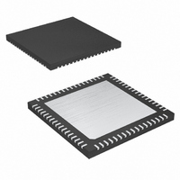
MAX2078CTK+ Maxim Integrated Products, MAX2078CTK+ Datasheet - Page 17

MAX2078CTK+
Manufacturer Part Number
MAX2078CTK+
Description
IC FRNT-END ULTRASOUND 8CH 68QFN
Manufacturer
Maxim Integrated Products
Type
Ultrasound Receiversr
Datasheet
1.MAX2078CTK.pdf
(26 pages)
Specifications of MAX2078CTK+
Applications
Medical Ultrasound Imaging, Sonar
Mounting Type
Surface Mount
Package / Case
68-TQFN Exposed Pad
Operating Supply Voltage
3.13 V to 3.47 V
Maximum Operating Temperature
+ 70 C
Mounting Style
SMD/SMT
Minimum Operating Temperature
0 C
Lead Free Status / RoHS Status
Lead free / RoHS Compliant
The MAX2078’s LNA is optimized for excellent dynamic
range and linearity performance characteristics, making it
ideal for ultrasound imaging applications. When the LNA
is placed in low-gain mode, the input resistance (R
being a function of the gain A (R
es by a factor of approximately 2. Consequently, the
switches that control the feedback resistance (R
be changed. For instance, the 100Ω mode in high gain
becomes the 200Ω mode in low gain (see Table 2).
The MAX2078’s VGAs are optimized for high linearity,
high dynamic range, and low output-noise performance,
all of which are critical parameters for ultrasound imaging
applications. Each VGA path includes circuitry for adjust-
ing analog gain, as well as an output buffer with differen-
tial output ports (OUT_+, OUT_-) for driving ADCs. See
the High-Level CW Mixer and Programmable Beamformer
Functional Diagram for details.
The VGA gain can be adjusted through the differential
gain control input VG+ and VG-. Set the differential gain
control input voltage at -3V for minimum gain and +3V for
maximum gain. The differential analog control common-
mode voltage is 1.65V (typ).
High-Level CW Mixer and Programmable Beamformer Functional Diagram
CW_IN8
CW_IN7
CW_IN6
CW_IN5
CW_IN4
CW_IN3
CW_IN2
CW_IN1
Variable-Gain Amplifier (VGA)
______________________________________________________________________________________
CLK
LO+
LO-
DIN
CS
Low-Noise Amplifier (LNA)
Octal-Channel Ultrasound Front-End
CHANNEL 1
I/Q PHASE
SELECTOR
DIVIDER
5
I Q
5-BIT
IN
SR
= R
CHANNEL 2
SELECTOR
I/Q PHASE
F
DIVIDER
5
I Q
/(1 + A)), increas-
5-BIT
SR
CHANNEL 3
I/Q PHASE
SELECTOR
DIVIDER
5
I Q
5-BIT
F
SR
) have to
CHANNEL 4
SELECTOR
I/Q PHASE
IN
DIVIDER
5
I Q
5-BIT
SR
),
with CW Doppler Mixers
CHANNEL 5
SELECTOR
I/Q PHASE
DIVIDER
5
I Q
5-BIT
The device is also optimized for quick overload recovery
for operation under the large input signal conditions that
are typically found in ultrasound input buffer imaging
applications. See the Typical Operating Characteristics
for an illustration of the rapid recovery time from a trans-
mit-related overload.
The MAX2078 CW mixers are designed using an active
double-balanced topology. The mixers achieve high
dynamic range and high linearity performance, with
exceptionally low thermal and jitter noise, ideal for ultra-
sound CWD signal reception. The octal quadrature
mixer array provides noise performance of 154dBc/Hz
at 1kHz offset from a 1.25MHz, 200mV
signal and a two-tone third-order ultrasound-specific
intermodulation product of -48.5dBc (typ). See the
Ultrasound-Specific IMD3 Specification section.
The octal array exhibits quadrature and in-phase differ-
ential current outputs (CQ+, CQ-, CI+, CI-) to produce
the total CWD beamformed signal. The maximum differ-
ential current output is typically 3mA
output compliance voltage ranges from 4.5V to 12V.
SR
CHANNEL 6
I/Q PHASE
SELECTOR
DIVIDER
5
I Q
5-BIT
SR
Octal Continuous-Wave (CW) Mixer
CLP
CHANNEL 7
SELECTOR
I/Q PHASE
DIVIDER
5
I Q
5-BIT
SR
CHANNEL 8
SELECTOR
I/Q PHASE
DIVIDER
5
I Q
5-BIT
SR
PD
MAX2078
Overload Recovery
CW_IOUT
CW_QOUT
DOUT
P-P
P-P
and the mixer-
input clutter
17


