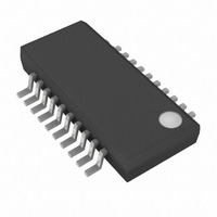
MAX3762EEP+ Maxim Integrated Products, MAX3762EEP+ Datasheet - Page 9

MAX3762EEP+
Manufacturer Part Number
MAX3762EEP+
Description
IC AMP LIMITING 622MBPS 20-QSOP
Manufacturer
Maxim Integrated Products
Type
Limiting Amplifierr
Datasheet
1.MAX3762EEP.pdf
(12 pages)
Specifications of MAX3762EEP+
Applications
Optical Networks
Mounting Type
Surface Mount
Package / Case
20-QSOP
Operating Supply Voltage
5 V
Supply Current
30 mA
Operating Temperature Range
+ 85 C
Available Set Gain
12.5 dB
Mounting Style
SMD/SMT
Number Of Channels
1
Power Dissipation
591 mW
Lead Free Status / RoHS Status
Lead free / RoHS Compliant
Many of the MAX3761/MAX3762’s specifications relate
to input-signal amplitude. When working with fiber optic
receivers, the input is usually expressed in terms of
average optical power and extinction ratio. The rela-
tions given in Table 1 are helpful for converting optical
power to input signal when designing with the
MAX3761/MAX3762.
Table 1. Optical-Power Relations*
* Assuming a 50% average input data duty cycle (true for SONET/ATM data).
In an optical receiver, the input voltage to the limiting
amplifier can be found by multiplying the relationship in
Table 1 with the photodiode responsivity (p) and tran-
simpedance amplifier gain (G).
Power and hysteresis are often expressed in decibels.
By definition, decibels are always 10log (power). At the
inputs to the MAX3761/MAX3762 limiting amplifier, the
power is V
increases by a factor of two, and the preamplifier is lin-
ear, then the voltage input to the MAX3761/MAX3762
also increases by a factor of two.
The optical power change is 10log(2x / x) = 10log(2) =
+3dB
At the MAX3761/MAX3762, the voltage change is:
10
__________Applications Information
PARAMETER
Average
Power
Extinction
Ratio
Optical Power
of a “1”
Optical Power
of a “0”
Signal
Amplitude
log
(
Converting Average Optical Power to
2V
V
IN
IN
IN
2
2
)
/R. If a receiver’s optical input power (x)
/ R
2
/ R
SYMBOL
_______________________________________________________________________________________
P
P
P1
P0
AVE
r
=
e
IN
Low-Power, 622Mbps Limiting Amplifiers
10
with Chatter-Free Power Detect for LANs
log(
P
r = 1 / P0
P
P
P
e
2
1 2
AVE
IN
0
2
=
=
)
P
=
Optical Hysteresis
= P0 + P1
2
P
P
=
P
Signal Amplitude
(
1
AVE
AVE
−
20
RELATION
P
r
0
log
/
e
r
(
=
e
+
r
e
( ( ) 2
2
)
1
P
/ 2
+
AVE
1
= + dB
)
(
r
r
e
e
6
−
+
1
1
)
In an optical receiver the dB change at the MAX3761/
MAX3762 will always equal 2x the optical dB change.
The MAX3761/MAX3762’s typical voltage hysteresis is
3.6dB. This provides an optical hysteresis of 1.8dB.
The receiver’s gain sensitivity defines the smallest signal
input that results in fully limited PECL-compatible data
outputs. Smaller signals result in nonlimited outputs. The
MAX3761/MAX3762’s input sensitivity (S
Optical gain sensitivity (in dBm) is:
In a receiver with G = 6kΩ, r
gain sensitivity is 510nW, or -32.9dBm.
As an example, a preamplifier with a 150kHz low-
frequency cutoff and a 950mVp-p maximum output has
the best performance with the following selections:
C
150kHz cutoff)
C
below f
C
equals 3MHz.
These selections should provide data-dependent jitter
less than 110ps p-p when the input consists of PRBS
data with no more than 72 consecutive bits.
Figure 4. Optical-Power Relations
IN
FILTER
AZ
OPTICAL
POWER
= 5.6nF, so that f
= 150pF, so that f
C
)
622Mbps ATM Component Selection
= 100pF, so that the integration frequency
10log
P
AVE
P1
P0
S
GAIN
⎡
⎢
⎣
S
2G
GAIN
C
= 4mV
= 15kHz (one decade below the
ρ
OC
x
r
r
e
< 1.5kHz (one decade
e
e
= 10, and ρ = 0.8A/W,
+
−
1
1
Input Sensitivity
x
1000
GAIN
) is 4mVp-p:
⎤
⎥
⎦
TIME
9


