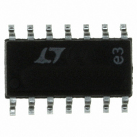
LT1256CS#PBF Linear Technology, LT1256CS#PBF Datasheet - Page 13

LT1256CS#PBF
Manufacturer Part Number
LT1256CS#PBF
Description
IC AMP VIDEO FADE CONTRLD 14SOIC
Manufacturer
Linear Technology
Type
Current Feedback Amplifierr
Datasheet
1.LT1256CSPBF.pdf
(24 pages)
Specifications of LT1256CS#PBF
Applications
Current Feedback
Number Of Circuits
1
-3db Bandwidth
40MHz
Slew Rate
300 V/µs
Current - Supply
14.5mA
Current - Output / Channel
40mA
Voltage - Supply, Single/dual (±)
5 V ~ 30 V, ±2.5 V ~ 15 V
Mounting Type
Surface Mount
Package / Case
14-SOIC (0.154", 3.90mm Width)
Rail/rail I/o Type
No
Number Of Elements
1
Common Mode Rejection Ratio
50dB
Input Offset Voltage
5mV
Input Bias Current
2.5uA
Single Supply Voltage (typ)
9/12/15/18/24/28V
Dual Supply Voltage (typ)
±3/±5/±9/±12V
Voltage Gain In Db
93dB
Power Supply Rejection Ratio
70dB
Power Supply Requirement
Single/Dual
Shut Down Feature
No
Single Supply Voltage (min)
5V
Single Supply Voltage (max)
30V
Dual Supply Voltage (min)
±2.5V
Dual Supply Voltage (max)
±15V
Technology
Bipolar
Operating Temp Range
0C to 70C
Operating Temperature Classification
Commercial
Mounting
Surface Mount
Pin Count
14
Package Type
SOIC N
Lead Free Status / RoHS Status
Lead free / RoHS Compliant
Available stocks
Company
Part Number
Manufacturer
Quantity
Price
APPLICATIONS
In low gain applications, R
the feedback resistors and therefore we can simplify the
equation to:
Note that the denominator causes a gain error due to the
open-loop gain (typically 0.1% for frequencies below
20kHz) and for mismatches in R
match in the feedback resistors results in a 0.25% error at
K = 0.5.
If we set R
at low frequencies) the above equation simplifies to:
This shows that the output fades linearly from input 2,
times its gain, to input 1, times its gain, as K goes from
0 to 1.
If only one input is used (for example, V
grounded, then the gain is proportional to K.
V
where A
V
V
O
O
1
KA
1
R
R
F1
G
V
G
R
V
sR C
1
O
KV
1
= R
OL
V
1
1
OL
1
R
R
F2
KV A
F
F
1
1
1
and assume R
1
U
R
R
R
V
K
1
G
F
F
R
R
1
1
1
INFORMATION
1
G
G
U
1
2
2
1
and
and R
K V
1
R
R
R
K V A
F
F
F
2
2
2
K
2
A
2
OL
F1
2
V
are small compared to
W
2
>> R
and R
V
2
1
F1
1
) and Pin 14 is
F2
R
R
(a 0.1% error
. A 1% mis-
F
G
2
2
U
Note that the denominator is the same as the noninverting
case. In low gain applications, R
compared to the feedback resistors and therefore we can
simplify the equation to:
Again, if we set R
error at low frequencies) the above equation simplifies to:
The 4-resistor difference amplifier yields the same result
as the inverting amplifier case, and the common mode
rejection is independent of K.
Similarly for the inverting case where the noninverting
inputs are grounded and the input voltages V
the normally grounded ends of R
V
O
V
where A
O
General Equation for the Inverting Amplifier Case
1
R
sR C
1
OL
V
O
R
OL
V
R
sR C
G
1
OL
1
KV
R
F1
OL
G
R
R
1
1
R
KV A
R
= R
KV
G
1
F
F
1
1
1
1
R
1
R
F2
1
and
R
G
F
V
1
K
1
R
R
and assume R
F
1
1
1
G
K V
K
2
1
R
R
A
1
F
G
2
V
1
1
LT1251/LT1256
1
R
2
R
F
K V A
G1
2
K
G
1
2
R
R
1
and R
2
G
F
and R
2
1
2
R
R
OL
V
F
2
2
2
K V
>> R
G2
R
R
1
G
F
R
, we get:
2
2
2
and V
2
1
2
F1
are small
K
R
R
1
(a 0.1%
13
G
F
2
2
2
drive
1


