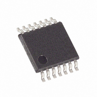
MAX4027EUD+ Maxim Integrated Products, MAX4027EUD+ Datasheet - Page 8

MAX4027EUD+
Manufacturer Part Number
MAX4027EUD+
Description
IC AMP VIDEO MUX 2CH 14-TSSOP
Manufacturer
Maxim Integrated Products
Datasheet
1.MAX4027EUD.pdf
(11 pages)
Specifications of MAX4027EUD+
Applications
2:1 Multiplexer-Amplifier
Number Of Circuits
3
-3db Bandwidth
225MHz
Slew Rate
1100 V/µs
Current - Supply
31mA
Current - Output / Channel
143mA
Voltage - Supply, Single/dual (±)
±4.5 V ~ 5.5 V
Mounting Type
Surface Mount
Package / Case
14-TSSOP
Lead Free Status / RoHS Status
Lead free / RoHS Compliant
cally 1.6kΩ. Parallel multiple devices to construct larger
switch matrices by connecting the outputs of several
devices together and disabling all but one of the paral-
leled amplifiers’ outputs. Two internal 800Ω thin-film
resistors set the MAX4027 to a fixed gain of +2.
Consider the impedance of the internal feedback resis-
tors when operating multiple MAX4027s in large multi-
plexer applications.
Drive EN low for normal operation. EN has internal pull-
down circuitry. The MAX4027 is enabled when EN is
unconnected.
The MAX4027 is well suited to drive short coaxial trans-
mission lines when the cable is terminated at both ends
(Figure 1) where the fixed gain of +2 compensates for the
loss in the back termination. Cable frequency response
may cause variations in the flatness of the signal.
The guaranteed input voltage range is ±1.25V.
Exceeding this value can cause unpredictable results,
including output clipping, excessive input current, and
switching delays.
The input multiplexer (mux) is controlled by a 3.3V
TTL/CMOS-compatible control input (see the Truth
Tables). Input capacitance is a constant, low 2pF and
input resistance is 17kΩ to GND for all input channels,
regardless of whether or not the channel is selected. All
logic levels (EN and A/B) default low if left unconnected.
225MHz, Triple, 2-Channel Video
Multiplexer-Amplifier
Figure 1. Video Line Driver
8
_______________________________________________________________________________________
75Ω CABLE
75Ω CABLE
Input Voltage Range
Video Line Driver
75Ω
75Ω
R
R
T
T
Multiplexer
IN_A
IN_B
A/B
MAX4027
EN
The MAX4027 has an extremely high bandwidth and
requires careful board layout. For best performance, use
constant-impedance microstrip or stripline techniques.
To realize the full AC performance of these high-speed
amplifiers, pay careful attention to power-supply
bypassing and board layout. The PC board should have
at least two layers: a signal and power layer on one
side, and a large, low-impedance ground plane on the
other side. The ground plane should be as free of voids
as possible. With multilayer boards, locate the ground
plane on an internal layer that incorporates no signal or
power traces.
Observe the following guidelines when designing the
board regardless of whether or not a constant-imped-
ance board is used.
1) Do not use wire-wrap boards or breadboards.
2) Do not use IC sockets; they increase parasitic
3) Keep lines as short and as straight as possible. Do
4) Observe high-frequency bypassing techniques to
5) Use surface-mount components. They generally
The bypass capacitors should include a 0.1µF ceramic
surface-mount capacitor between each supply pin and
the ground plane, located as close to the package as
capacitance and inductance.
not make 90° turns; round all corners.
maintain the amplifier’s accuracy and stability.
have shorter bodies and lower parasitic reactance,
yielding better high-frequency performance than
through-hole components.
OUT_
Layout and Power-Supply Bypassing
75Ω
R
T
75Ω CABLE
R
75Ω
T


