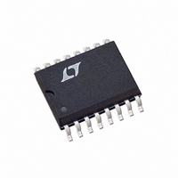
LT1204CSW Linear Technology, LT1204CSW Datasheet - Page 17

LT1204CSW
Manufacturer Part Number
LT1204CSW
Description
IC VIDEOMUX CFA 75MHZ 4IN 16SOIC
Manufacturer
Linear Technology
Datasheet
1.LT1204CSWPBF.pdf
(20 pages)
Specifications of LT1204CSW
Applications
4:1 Multiplexer-Amplifier
Number Of Circuits
1
-3db Bandwidth
75MHz
Slew Rate
1000 V/µs
Current - Supply
19mA
Current - Output / Channel
125mA
Voltage - Supply, Single/dual (±)
10 V ~ 30 V, ±5 V ~ 15 V
Mounting Type
Surface Mount
Package / Case
16-SOIC (0.300", 7.50mm Width)
Lead Free Status / RoHS Status
Contains lead / RoHS non-compliant
Other names
LT1204CS
Available stocks
Company
Part Number
Manufacturer
Quantity
Price
Part Number:
LT1204CSW
Manufacturer:
LT/凌特
Quantity:
20 000
Part Number:
LT1204CSW#PBF
Manufacturer:
LINEAR/凌特
Quantity:
20 000
Part Number:
LT1204CSW#TRPBF
Manufacturer:
LINEAR/凌特
Quantity:
20 000
Programable Gain Amplifier (PGA)
Two LT1204s and seven resistors make a Programable
Gain Amplifier with a 128-to-1 gain range. The gain is
proportional to 2
select logic. An input attenuator alters the input signal
TYPICAL
V
IN
= 62.5mV
499
Programable Gain Amplifier Accepts Inputs
P-P
TO 8V
249
A
P-P
PPLICATI
N
from 62.5mV
where N is the 3-bit binary value of the
TWISTED PAIR
124
124
CABLE
*OPTIONAL
13
13
P-P
100
1
3
5
7
1
3
5
7
O
+
+
+
+
–
+
+
+
+
–
to 8V
LT1204
LT1204
U
#1
#2
P-P
S
1.5k
1.5k
68
68
1k*
1k*
1204 TA03
4-Input Differential Receiver
1k*
1k*
V
OUT
= 1V
–IN 1
–IN 2
–IN 3
–IN 4
IN 1
IN 2
IN 3
IN 4
P-P
1k
1k
by 1, 0.5, 0.25 and 0.125 to form an amplifier with a gain
of 16, 8, 4, 2, when LT1204 #1 is selected. LT1204 #2
is connected to the same attenuator. When enabled
(LT1204 #1 disabled), it results in gain of 1, 0.5, 0.25 and
0.125. The wide input common mode range of the
LT1204 is needed to accept inputs of 8V
4-Input Differential Receiver
LT1204s can be connected inverting and noninverting as
shown to make a 4-input differential receiver. The receiver
can be used to convert differential signals sent over a low
cost twisted pair to a single-ended output or used in video
loop-thru connections. The logic inputs A0 and A1 are tied
together because the same channels are selected on each
LT1204. By using the Disable feature, the number of
differential inputs can be increased by adding pairs of
LT1204s and tying the outputs of the noninverting LT1204s
(#1) together. Switching transients are reduced in this
receiver because the transient from LT1204 #2 subtracted
from the transient of LT1204 #1.
+
+
+
+
–
+
+
+
+
–
A0
A0
A0
LT1204
LT1204
A1
A1
A1
#1
#2
SHDN
SHDN
SHDN
EN
EN
EN
1k
1k
1204 TA04
75
V
75
OUT
P-P
LT1204
.
17


