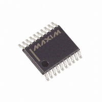
DS3508E+ Maxim Integrated Products, DS3508E+ Datasheet

DS3508E+
Specifications of DS3508E+
Related parts for DS3508E+
DS3508E+ Summary of contents
Page 1
... Analog Supply ♦ 2.7V to 5.5V Digital Supply ♦ 20-Pin TSSOP Package supply. DD ♦ Address Pin Allows Two DS3508s to Reside on C-compatible serial the Same I Applications PART DS3508E+ DS3508E+T&R + Denotes a lead-free package. T&R = Tape and reel. 8 SOURCE DRIVER LIQUID-CRYSTAL DISPLAY Features , typ ...
Page 2
I C, 8-Channel Gamma Buffer with EEPROM ABSOLUTE MAXIMUM RATINGS Voltage Range on V and DD VHH Relative to GND ..........................................-0.5V to +16V Voltage Range on VHM, VLM, and VLL Relative to GND............................................-0.5V to +12V Voltage Range on V ...
Page 3
I C, 8-Channel Gamma Buffer with EEPROM OUTPUT ELECTRICAL CHARACTERISTICS (V = +2.7V to +5.5V 15.5V PARAMETER SYMBOL Gamma DAC Resolution Integral Nonlinearity Error Differential Nonlinearity Error Output Voltage Range: GM1–GM4 Output Voltage ...
Page 4
I C, 8-Channel Gamma Buffer with EEPROM ELECTRICAL CHARACTERISTICS (continued +2.7V to +5.5V -45°C to +95°C, timing referenced PARAMETER SYMBOL SDA Output Low Voltage Input Capacitance on A0, ...
Page 5
I C, 8-Channel Gamma Buffer with EEPROM (V = 15.0V 5.0V +25°C, unless otherwise noted ANALOG SUPPLY CURRENT vs. TEMPERATURE 4.0 3.5 3.0 2.5 2.0 1.5 1.0 0.5 0 -45 -25 -5 ...
Page 6
I C, 8-Channel Gamma Buffer with EEPROM VHH SDA SCL INTERFACE A0 CONTROL LOGIC CONTROL REGISTERS VHM VLM VLL GND 6 _______________________________________________________________________________________ Functional Diagram 8-BIT SRAM 1 DAC ...
Page 7
I C, 8-Channel Gamma Buffer with EEPROM PIN NAME TYPE 1 SCL Input Input/ 2 SDA Output 3 GND Ground 4 A0 Input Reference 5 VHH Input Reference 6 VHM Input Reference 7 VLM Input Reference 8 VLL Input ...
Page 8
I C, 8-Channel Gamma Buffer with EEPROM On power-up, the gamma data that is stored in each channel’s EEPROM register is loaded into the corre- sponding SRAM registers. The volatile CR register pow- ers up as 00h, setting the ...
Page 9
I C, 8-Channel Gamma Buffer with EEPROM Table 1. DAC Voltage/Data Relationship for Selected Codes DATA (BINARY) 0000 0000 0000 0001 0000 0010 0000 0011 0000 1111 0011 1111 0111 1111 1111 1101 1111 1110 1111 1111 MSB 1 ...
Page 10
I C, 8-Channel Gamma Buffer with EEPROM Memory Organization Memory Description The list of registers/memory contained in the DS3508 is shown in the memory map (Table 2). Each of the GMx Table 2. Memory Map NAME GM1 GM2 GM3 ...
Page 11
I C, 8-Channel Gamma Buffer with EEPROM Serial Interface Description The following terminology is commonly used to describe data transfers. (See Figure 4 and the I Characteristics table for additional information.) Master device: ...
Page 12
I C, 8-Channel Gamma Buffer with EEPROM Byte read: A byte read is an 8-bit information transfer from the slave to the master plus a 1-bit ACK or NACK from the master to the slave. The 8 bits of ...
Page 13
I C, 8-Channel Gamma Buffer with EEPROM 2 TYPICAL I C WRITE TRANSACTION MSB LSB START R/W READ/ SLAVE WRITE ADDRESS* 2 EXAMPLE I C TRANSACTIONS (WHEN A0 IS CONNECTED TO GND) ...
Page 14
... Maxim cannot assume responsibility for use of any circuitry other than circuitry entirely embodied in a Maxim product. No circuit patent licenses are implied. Maxim reserves the right to change the circuitry and specifications without notice at any time. 14 ____________________Maxim Integrated Products, 120 San Gabriel Drive, Sunnyvale, CA 94086 408-737-7600 © 2008 Maxim Integrated Products DESCRIPTION = +25° ...


