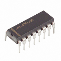
MAX468CPE Maxim Integrated Products, MAX468CPE Datasheet - Page 11

MAX468CPE
Manufacturer Part Number
MAX468CPE
Description
IC 2CH QUAD VIDEO BUFF 16 DIP
Manufacturer
Maxim Integrated Products
Datasheet
1.MAX470EPE.pdf
(16 pages)
Specifications of MAX468CPE
Applications
Buffer
Number Of Circuits
4
-3db Bandwidth
100MHz
Slew Rate
200 V/µs
Current - Supply
85mA
Voltage - Supply, Single/dual (±)
±4.75 V ~ 5.25 V
Mounting Type
Through Hole
Package / Case
16-DIP (0.300", 7.62mm)
Lead Free Status / RoHS Status
Contains lead / RoHS non-compliant
Available stocks
Company
Part Number
Manufacturer
Quantity
Price
Part Number:
MAX468CPE
Manufacturer:
MAXIM/美信
Quantity:
20 000
Table 1a. Amplifier and Channel Selection
with LE = V+
When LE is connected to ground, the E
transparent and independent of C
all MAX463–MAX466 devices to be simultaneously shut
down, regardless of the C
LE to ground and connect all E
5a). For the MAX464 and MAX466, LE must be hard-
wired to either V+ or ground (rather than driving LE with
a gate) to prevent crosstalk from the digital inputs to
IN0A.
Figure 5. (a) Simultaneous Shutdown of all MAX463–MAX466, (b) Enable (
C
NOTE: ISOLATION RESISTORS,
—
0
0
0
1
S
–
IF REQUIRED, NOT SHOWN.
E
—
X
0
0
1
N
–
SHUTDOWN
A0
X
X
0
1
______________________________________________________________________________________
Enables amplifier outputs.
Selects channel A.
Enables amplifier outputs.
Selects channel B.
Disables amplifiers. Outputs high-Z.
Latches all input registers.
Changes nothing.
—
S
–
input state. Simply connect
—
N
EN
–
LE
LE
EN
FUNCTION
—
inputs together (Figure
MAX463–
MAX463–
S
MAX466
MAX466
–
(a)
activity. This allows
RGB Video Switches and Buffers
—
N
–
register is
Two-Channel, Triple/Quad
Another option for output disable is to connect LE to V+,
parallel the outputs of several MAX463-MAX466s, and use
E
(Figure 5b).
When the outputs are disabled, the off isolation from
the analog inputs to the amplifier outputs is typically
70dB at 10MHz, all inputs driven with a 4V
wave and a 150Ω load impedance. Figure 6 shows the
test circuits used to measure isolation and crosstalk.
+5V
Table 1b. Amplifier and Channel Selection
with LE = GND
—
+5V
N
–
C
—
0
0
0
0
1
1
S
to individually disable all devices but the one in use
–
–
E
—
EN
EN
AO
CS
AO
CS
LE
LE
N
–
) Register Latched by
E
—
0
0
1
1
0
1
N
MAX463–
–
MAX463–
MAX466
MAX466
(b)
A0
0
1
0
1
X
X
Enables amplifier outputs.
Selects channel A.
Enables amplifier outputs.
Selects channel B.
Disables amplifiers. Outputs high-Z.
A0 register = channel A
Disables amplifiers. Outputs high-Z.
A0 register = channel B
Enables amplifier outputs, latches A0
register, programs outputs to output A
or B, according to the setting of A0 at
C
Disables amplifiers. Outputs high-Z.
—
S
–
's last edge.
–
C
—
S
–
FUNCTION
P-P
sine
11


