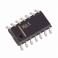
MAX4298ESD+ Maxim Integrated Products, MAX4298ESD+ Datasheet - Page 8

MAX4298ESD+
Manufacturer Part Number
MAX4298ESD+
Description
IC STEREO DVR AUDIO 14-SOIC
Manufacturer
Maxim Integrated Products
Type
PSRR Stereo Driverr
Datasheet
1.MAX4298ESDT.pdf
(14 pages)
Specifications of MAX4298ESD+
Applications
Desktop Audio, MP3, USB
Mounting Type
Surface Mount
Package / Case
14-SOIC (3.9mm Width), 14-SOL
Lead Free Status / RoHS Status
Lead free / RoHS Compliant
The amplifiers exhibit better than 115dB of DC power-
supply rejection and 93dB at 20kHz. The output ampli-
fiers are capable of driving a 1.5V
load with 0.0008% distortion. They can also drive 32Ω
headphones to 1.2V
+3.3V, the linear regulator can output 100mA of current.
The common-mode bias point for the amplifiers is set to
2.25V by internal circuitry that has two functions. It pro-
vides a clickless/popless power-up/power-down wave-
form for the amplifiers. Also, it generates a ground-
referenced bias voltage with ultra-high power-supply
rejection ratio (PSRR). BIAS should be bypassed with 1µF
to GND.The output impedance of the BIAS pin is 50kΩ.
The MAX4298/MAX4299 are designed for high-fidelity
audio performance into AC-coupled loads. The design
techniques achieve a clickless/popless power-up
sequence, and the use of a low-current standby supply
(SV
combination allows clickless/popless power-down. A
clickless/popless mute function is also provided to main-
tain a low impedance output when the input signal is
switched off.
The MAX4298/MAX4299 have a MUTE pin that allows the
user to mute the outputs of the device. This feature dis-
connects the input signal from the power amplifiers when
a logic high is present at the MUTE pin. To ensure proper
functionality, the MUTE pin should always be tied to either
V
outputs. REG, BIAS, and MICOUT are unaffected. OUT1
and OUT2 are muted, but remain in a low-impedance
state to ensure clickless/popless operation.
Ultra-High PSRR Stereo Drivers +
Microphone Amp + 100mA Linear Regulator
Figure 1. MAX4298 Block Diagram
8
CC
CC
_______________________________________________________________________________________
or GND. MUTE only affects the headphone driver
) or external Schottky diode/reservoir capacitor
C
BYPASS
BIAS
IN1
IN2
Clickless/Popless Function
RMS
MAX4298
50kΩ
+
+
_
_
with 0.02% distortion. At
2.25V
RMS
Mute Function
SV
V
OUT1
MUTE
OUT2
GND
signal into 10kΩ
CC
CC
BIAS
The MAX4298/MAX4299 provide a fully clickless power-
down sequence. SV
a low-current +5V power source, but alternatively can be
connected with a reservoir capacitor to ground and a
Schottky diode to V
higher provides enough charge for the clickless power-
down sequence when C
C
Short to V
The headphone driver amplifier is a class AB amplifier
designed to drive 16Ω loads. The amplifiers have innov-
ative architectures for both the input and output stages
to achieve ultra-high PSRR while maintaining rail-to-rail
output drive capability. The output stage can drive high
capacitive loads encountered when driving long cables
used for desktop speakers or headphones.
The MAX4299 provides a microphone preamplifier that
is a low-power version of the audio amplifier. It is intend-
ed to be used for low-level signal amplification. This
microphone preamplifier provides rail-to-rail output with
very high PSRR.
Figure 2. MAX4299 Block Diagram
BIAS
, increase the reservoir capacitor accordingly.
CC
Microphone Preamplifier (MAX4299)
if clickless power-down is not needed.
MICOUT
C
BYPASS
MUTE
BIAS
REG
IN1
IN2
FB
CC
CC
. A reservoir capacitor of 220µF or
11kΩ
18.4kΩ
normally should be connected to
BIAS
+
_
+
_
+
_
MAX4299
50kΩ
= 1µF. For larger values of
+
1.233V
_
2.25V
Driver Amplifier
V
SV
OUT1
MICIN
GND
PGND
REGON
OUT2
N.C.
CC
CC
SV
CC


