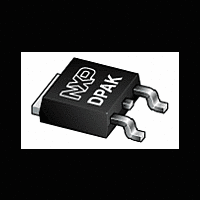
BT151S-650L NXP Semiconductors, BT151S-650L Datasheet

BT151S-650L
Available stocks
Related parts for BT151S-650L
BT151S-650L Summary of contents
Page 1
... Pinning Pin Description 1 cathode (K) 2 anode (A) 3 gate (G) mb mounting base; connected to anode 500 V (BT151S-500L/R) 500 V (BT151S-500L/R) 650 V (BT151S-650L/R) 650 V (BT151S-650L/R) 800 V (BT151S-800R) 800 V (BT151S-800R) Simplified outline Product data sheet I Surface-mounted package I Static switching I Protection circuits I I 120 ms) ...
Page 2
... The rate of rise of current should not exceed 15A/ s. BT151S_SER_L_R_5 Product data sheet Description plastic single-ended surface-mounted package; 3 leads (one lead cropped) SOT428 Conditions BT151S-500L; BT151S-500R BT151S-650L; BT151S-650R BT151S-800R BT151S-500L; BT151S-500R BT151S-650L; BT151S-650R BT151S-800R half sine wave; T 103 C; mb see Figure 1 all conduction angles; see and 5 half sine wave ...
Page 3
... TSM (A) 120 Fig 2. Non-repetitive peak on-state current as a function of the number of sinusoidal current cycles; maximum values BT151S_SER_L_R_5 Product data sheet 2 Rev. 05 — 9 October 2006 BT151S series L and R 1.9 2.2 conduction form angle factor (degrees 2.8 90 2.2 120 1.9 180 1 ...
Page 4
... Hz; T 103 C mb Fig 4. RMS on-state current as a function of surge duration; maximum values BT151S_SER_L_R_5 Product data sheet BT151S series L and 001aaa954 16 I T(RMS) ( surge duration (s) Fig 5. RMS on-state current as a function of mounting Rev. 05 — 9 October 2006 ...
Page 5
... Fig 6. Transient thermal impedance from junction to mounting base as a function of pulse width BT151S_SER_L_R_5 Product data sheet BT151S series L and R Conditions see Figure 6 mounted on an FR4 printed-circuit board; see Figure Rev. 05 — 9 October 2006 Min ...
Page 6
... BT151S_SER_L_R_5 Product data sheet BT151S series L and R Conditions 100 mA; see Figure BT151S-500L BT151S-500R BT151S-650L BT151S-650R BT151S-800R 100 mA; see D GT Figure 100 mA; see D GT Figure see Figure 100 mA ...
Page 7
... T = 125 C; typical values j ( 125 C; maximum values j ( maximum values j Fig 9. On-state current as a function of on-state voltage BT151S_SER_L_R_5 Product data sheet BT151S series L and R 001aaa953 GT( 100 150 Fig 8. Normalized gate trigger current as a function of ...
Page 8
... NXP Semiconductors H( Fig 11. Normalized holding current as a function of junction temperature BT151S_SER_L_R_5 Product data sheet BT151S series L and R 001aaa950 / 100 150 (1) R (2) Gate open circuit Fig 12. Critical rate of rise of off-state voltage as a function of junction temperature ...
Page 9
... scale min min 5.46 0.56 6.22 6.73 4.0 4.45 5.00 0.20 5.98 6.47 REFERENCES JEDEC JEITA SC-63 TO-252 Rev. 05 — 9 October 2006 BT151S series L and min 10.4 2.95 0.5 2.285 4.57 9.6 2.55 EUROPEAN PROJECTION Thyristors SOT428 max 0.9 0.2 0.2 0.5 ISSUE DATE ...
Page 10
... NXP Semiconductors 8. Mounting Fig 14. SOT428: minimum pad size for surface-mounting BT151S_SER_L_R_5 Product data sheet 7.0 2.15 2.5 Plastic meets requirements of UL94 V-O at 3.175 mm Rev. 05 — 9 October 2006 BT151S series L and R 7.0 1.5 4.57 001aab021 © NXP B.V. 2006. All rights reserved. Thyristors ...
Page 11
... The format of this data sheet has been redesigned to comply with the new identity guidelines of NXP Semiconductors. • Legal texts have been adapted to the new company name where appropriate. • Added type numbers BT151S-500L and BT151S-650L BT151S_SERIES_4 20040609 (9397 750 13161) BT151S_SERIES_3 ...
Page 12
... For additional information, please visit: For sales office addresses, send an email to: BT151S_SER_L_R_5 Product data sheet BT151S series L and R [3] Definition This document contains data from the objective specification for product development. This document contains data from the preliminary specification. ...
Page 13
... Trademarks . . . . . . . . . . . . . . . . . . . . . . . . . . . 12 11 Contact information Contents . . . . . . . . . . . . . . . . . . . . . . . . . . . . . . 13 BT151S series L and R Please be aware that important notices concerning this document and the product(s) described herein, have been included in section ‘Legal information’. © NXP B.V. 2006. For more information, please visit: http://www.nxp.com For sales office addresses, please send an email to: salesaddresses@nxp.com ...


