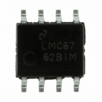
LMC6762BIM/NOPB National Semiconductor, LMC6762BIM/NOPB Datasheet - Page 11

LMC6762BIM/NOPB
Manufacturer Part Number
LMC6762BIM/NOPB
Description
IC COMP DUAL MICRPWR CMOS 8-SOIC
Manufacturer
National Semiconductor
Type
General Purposer
Datasheet
1.LMC6762AIMNOPB.pdf
(14 pages)
Specifications of LMC6762BIM/NOPB
Number Of Elements
2
Output Type
Push-Pull, Rail-to-Rail
Voltage - Supply
2.7 V ~ 15 V, ±1.35 V ~ 7.5 V
Mounting Type
Surface Mount
Package / Case
8-SOIC (0.154", 3.90mm Width)
Comparator Type
Micropower
No. Of Comparators
2
Response Time
4µs
Ic Output Type
Push Pull
Supply Current
25µA
Supply Voltage Range
2.7V To 15V
Amplifier Case Style
SOIC
No. Of Pins
8
Rohs Compliant
Yes
Dc
1012
Lead Free Status / RoHS Status
Lead free / RoHS Compliant
Other names
*LMC6762BIM
*LMC6762BIM/NOPB
LMC6762BIM
*LMC6762BIM/NOPB
LMC6762BIM
Available stocks
Company
Part Number
Manufacturer
Quantity
Price
Company:
Part Number:
LMC6762BIM/NOPB
Manufacturer:
TI
Quantity:
10 000
Typical Applications
ONE-SHOT MULTIVIBRATOR
A monostable multivibrator has one stable state in which it
can remain indefinitely. It can be triggered externally to
another quasi-stable state. A monostable multivibrator can
thus be used to generate a pulse of desired width.
The desired pulse width is set by adjusting the values of C
and R
determine the magnitude of the input trigger pulse. The
LMC6762 will change state when V
vides a rapid discharge path for capacitor C
end of the pulse. The diode also prevents the non-inverting
input from being driven below ground.
BI-STABLE MULTIVIBRATOR
A bi-stable multivibrator has two stable states. The reference
voltage is set up by the voltage divider of R
applied to the SET terminal will switch the output of the
comparator high. The resistor divider of R
clamps the non-inverting input to a voltage greater than the
reference voltage. A pulse applied to RESET will now toggle
the output low.
4
. The resistor divider of R
FIGURE 6. One-Shot Multivibrator
FIGURE 7. Bi-Stable Multivibrator
1
and R
1
<
V
1
2
2
, R
2
. Diode D
can be used to
2
and R
4
to reset at the
, and R
3
. A pulse
01232015
01232014
2
5
now
pro-
2
11
ZERO CROSSING DETECTOR
A voltage divider of R
voltage V
resistance of R
switch when V
below −0.7V. The voltage divider of R
V
setup to ensure rapid output voltage transitions.
OSCILLATOR
Figure 9 shows the application of the LMC6762 in a square
wave generator circuit. The total hysteresis of the loop is set
by R
discharge paths for the capacitor C. The charge path is set
through R
the RC time constant of R
path for the capacitor is set by R
between the pulses can be changed by varying R
pulse width can be altered by R
output can be changed by varying both R
2
from going below ground. A small amount of hysteresis is
1
, R
2
1
4
and R
FIGURE 9. Square Wave Generator
FIGURE 8. Zero Crossing Detector
at the non-inverting input. By making the series
and D
IN
1
3
= 0. Diode D
and R
. R
1
. So, the pulse width t
4
and R
4
2
and R
equal to R
4
and C. Similarly, the discharge
5
1
provide separate charge and
insures that V
5
5
and D
4
establishes a reference
. The frequency of the
2
5
, the comparator will
and R
2
1
. Thus, the time t
4
is determined by
and R
3
3
then prevents
never drops
www.national.com
5
5
01232016
.
, and the
01232019
2


