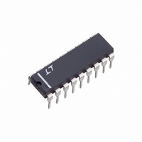
LTC1040CN Linear Technology, LTC1040CN Datasheet - Page 3

LTC1040CN
Manufacturer Part Number
LTC1040CN
Description
IC COMPARATOR LOW PWR DUAL 18DIP
Manufacturer
Linear Technology
Series
LTCMOS™r
Type
General Purposer
Datasheet
1.LTC1040CNPBF.pdf
(12 pages)
Specifications of LTC1040CN
Number Of Elements
2
Output Type
CMOS, TTL
Voltage - Supply
2.8 V ~ 16 V, ±2.8 V ~ 8 V
Mounting Type
Through Hole
Package / Case
18-DIP (0.300", 7.62mm)
Lead Free Status / RoHS Status
Contains lead / RoHS non-compliant
Available stocks
Company
Part Number
Manufacturer
Quantity
Price
Company:
Part Number:
LTC1040CN
Manufacturer:
ST
Quantity:
6 222
Part Number:
LTC1040CN#PBF
Manufacturer:
LINEAR/凌特
Quantity:
20 000
ELECTRICAL CHARACTERISTICS
temperature range otherwise specifications are at T
SYMBOL
V
V
R
f
Note 1: Absolute Maximum Ratings are those values beyond which the life
of a device may be impaired.
Note 2: Applies over input voltage range limit and includes gain
uncertainty.
Note 3: Tracking error = (V
Note 4: R
R
TYPICAL PERFOR A CE CHARACTERISTICS
S
IH
IL
EXT
IN
20
18
16
14
12
10
= 1/(f
300
250
100
8
6
4
2
0
200
150
50
2
0
Peak Supply Current
vs Supply Voltage
Response Time
vs Supply Voltage
2
S
IN
T
A
• 33pF).
4
is guaranteed by design and is not tested.
= 25 C
PARAMETER
STROBE Input (Note 7)
Logic “1” Input Voltage
Logic “0” Input Voltage
External Timing Resistor
Sampling Frequency
4
SUPPLY VOLTAGE, V
6
SUPPLY VOLTAGE, V
6
8
–55 C
8
10
IN1
10
– V
125 C
+
12
(V)
IN2
12
+
(V)
LTC1040 • TPC01
25 C
)/ V
W
14
LTL1040 • TPC04
14
IN1
.
16
U
16
CONDITIONS
V
V
Resistor Tied Between V
R
+
+
EXT
= 5.25V
= 4.75V
10
10
10
10
10
= 1M, C
2.2
2.0
1.8
1.6
1.4
1.2
1.0
0.8
0.6
A
10
11
9
8
7
= 25 C. Test conditions: V
1
0
Input Resistance
vs Sampling Frequency
Normalized Sampling Frequency
vs Supply Voltage and Temperature
T
A
= 25 C
EXT
2
The denotes the specifications which apply over the full operating
SAMPLING FREQUENCY, f
= 0.1 F
10
SUPPLY VOLTAGE, V
4
T
A
= 125 C
6
+
10
and OSC Pin
Note 5: Average supply current = t
Note 6: Response time is set by an internal oscillator and is independent
of overdrive voltage.
Note 7: Inputs and outputs also capable of meeting EIA/JEDEC B series
CMOS specifications.
8
2
10
+
(V)
10
S
12
T
(Hz)
A
3
+
C = 0.1 F
LTC1040 • TPC05
LTC1040 • TPC02
= –55 C
= 5V, V
R = 1M
14
10
16
4
–
= – 5V, unless otherwise specified
MIN
100
2.0
10
10
0.1
0.2
0.4
0.6
0.8
1.0
1.2
1.4
1.6
1.8
2.0
10
1
100k
0
LTC1040M/LTC1040C
3
2
D
V
vs Load Current
0
Sampling Rate vs R
• l
P-P
V
S(ON)
+
1
= 2.8V
C
Output Voltage
EXT
2
TYP
1.6
1.0
• f
5
C
LOAD CURRENT, I
= 1 F
EXT
S
3
+ (1 – t
= 0.1 F
4
R
C
EXT
LTC1040
EXT
1M
5
( )
D
10,000
= 0.01 F
V
MAX
x f
0.8
6
+
EXT
C
L
= 10V
S
EXT
(mA)
) • l
C
7
, C
EXT
= 1000pF
S(OFF)
V
8
LTC1040 • TPC06
EXT
= 0.05 F
LT1040 • TPC03
+
V
= 16V
+
= 5V
9
UNITS
.
1040fa
3
10M
10
k
Hz
V
V


