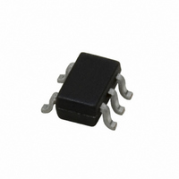
LMV7291MGX/NOPB National Semiconductor, LMV7291MGX/NOPB Datasheet - Page 4

LMV7291MGX/NOPB
Manufacturer Part Number
LMV7291MGX/NOPB
Description
IC COMPARATOR 1.8V R-R LP SC70-5
Manufacturer
National Semiconductor
Series
PowerWise®r
Type
General Purposer
Datasheet
1.LMV7291MGNOPB.pdf
(14 pages)
Specifications of LMV7291MGX/NOPB
Number Of Elements
1
Output Type
CMOS, Push-Pull, Rail-to-Rail
Voltage - Supply
1.8 V ~ 5 V, ±0.9 V ~ 2.5 V
Mounting Type
Surface Mount
Package / Case
6-TSSOP (5 lead), SC-88A, SOT-353
Lead Free Status / RoHS Status
Lead free / RoHS Compliant
Other names
LMV7291MGX
www.national.com
V
V
V
CMRR
PSRR
I
t
t
LEAKAGE
PHL
PLH
Symbol
Symbol
5V Electrical Characteristics
OH
OL
CM
Unless otherwise specified, all limits guaranteed for T
tremes.
5.0V AC Electrical Characteristics
Unless otherwise specified, all limits guaranteed for T
V
Note 1: Absolute Maximum Ratings indicate limits beyond which damage to the device may occur. Operating Ratings indicate conditions for which the device is
intended to be functional, but specific performance is not guaranteed. For guaranteed specifications and the test conditions, see the Electrical Characteristics.
Note 2: Human body model, 1.5kΩ in series with 100pF.
Note 3: The maximum power dissipation is a function of T
P
Note 4: Typical values represent the most likely parametric norm.
Note 5: All limits are guaranteed by testing or statistical analysis.
Note 6: Machine Model, 0Ω in series with 200pF.
Note 7: Offset Voltage average drift determined by dividing the change in V
Note 8: Electrical Table values apply only for factory testing conditions at the temperature indicated. Factory testing conditions result in very limited self-heating of
the device such that T
Absolute Maximum Ratings indicate junction temperature limits beyond which the device may be permanently degraded, either mechanically or electrically.
D
−
. Boldface limits apply at the temperature extremes.
= (T
J(MAX)
Output Voltage High
Output Voltage Low
Input Common Voltage Range
Common Mode Rejection Ratio
Power Supply Rejection Ratio
Output Leakage Current
Propagation Delay
(High to Low)
Propagation Delay
(Low to High)
- T
A
)/θ
JA
J
. All numbers apply for packages soldered directly into a PC board.
= T
A
. No guarantee of parametric performance is indicated in the electrical tables under conditions of internal self heating where T
Parameter
Parameter
I
I
I
I
CMRR
0
V
V
Input Overdrive = 20mV
Load = 50pF//5kΩ
Input Overdrive = 50mV
Load = 50pF//5kΩ
Input Overdrive = 20mV
Load = 50pF//5kΩ
Input Overdrive = 50mV
Load = 50pF//5kΩ
O
O
O
O
J(MAX)
(Continued)
+
O
<
= 0.5mA
= 4.0mA
= −0.5mA
= −4.0mA
= 1.8V to 5V
= 5V
V
, θ
J
J
CM
= 25˚C, V
= 25˚C, V
>
JA
, and T
Conditions
<
45dB
Condition
OS
5.0V
at temperature extremes into the total temperature change.
4
A
. The maximum allowable power dissipation at any ambient temperature is
+
+
= 5V, V
= 5.0V, V
−
= 0V. Boldface limits apply at the temperature ex-
−
= 0V, V
(Note 5)
(Note 5)
4.93
4.70
−0.1
Min
Min
47
55
CM
= 0.5V, V
(Note 4)
(Note 4)
2100
1380
1800
1100
4.96
4.77
Typ
Typ
225
27
78
80
2
O
= V
+
/2 and R
(Note 5)
(Note 5)
Max
Max
300
5.1
70
L
>
1MΩ to
Units
Units
J
mV
dB
dB
pA
ns
ns
ns
ns
>
V
V
T
A
.


