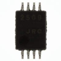
NJM2509V-TE1# NJR, NJM2509V-TE1# Datasheet

NJM2509V-TE1#
Specifications of NJM2509V-TE1#
NJM#2509V-TE1TR
NJM#2509V-TE1TR
NJM2509V-TE1#TR
Available stocks
Related parts for NJM2509V-TE1#
NJM2509V-TE1# Summary of contents
Page 1
... Impose voltage fixed internally to white level and black level. • Internal 6dB AMP. (Input : 0.5V • Package Outline SSOP8 • Bipolar Technology ■ RECOMMENDED OPERATING CONDITION • Operating Voltage ■ APPLICATION • Video Camera ■ BLOCK DIAGRAM Ver.2004-02-17 Output : 1 P-P P 4.5V to 5.1V NJM2509V NJM2509 ■ PACKAGE OUTLINE NJM2509V - 1 - ...
Page 2
NJM2509 ■ ABSOLUTE MAXIMUM RATINGS PARAMETER Supply Voltage Power Dissipation Operating Temperature Range Storage Temperature Range ■ ELECTRICAL CHARACTERISTICS PARAMETER SYMBOL Operating Current I Clamp Voltage V Bias Voltage V Voltage Gain G Frequency Characteristic G Background Voltage V CHR, ...
Page 3
TEST CIRCUIT Ver.2004-02-17 NJM2509 - 3 - ...
Page 4
NJM2509 ■ TERMINLAL EXPLANATION UNIT FUNCTION PIN No. Input 2.5V clamp 0.5V Y-signal PP 1 YIN or Compozitto signal 2 GND GROUND Input 2.5V Bias, 3 CIN 0.5V C-signal PP Character signal Input Pin 4 SET H Black level i ...
Page 5
APPLICATION This IC requires 1MΩ resistance between INPUT and GND pin for clamp type input since the minute current causes an unstable pin voltage. Ver.2004-02-17 NJM2509 [CAUTION] The specifications on this databook are only given for information , without ...


