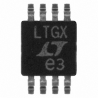
LT1675CMS8-1#PBF Linear Technology, LT1675CMS8-1#PBF Datasheet - Page 8

LT1675CMS8-1#PBF
Manufacturer Part Number
LT1675CMS8-1#PBF
Description
IC MUX RGB SGL HS W/CFA 8-MSOP
Manufacturer
Linear Technology
Type
MUXr
Datasheet
1.LT1675CS8-1PBF.pdf
(16 pages)
Specifications of LT1675CMS8-1#PBF
Applications
Drivers, Processing, Switching
Mounting Type
Surface Mount
Package / Case
8-MSOP, Micro8™, 8-uMAX, 8-uSOP,
Lead Free Status / RoHS Status
Lead free / RoHS Compliant
Available stocks
Company
Part Number
Manufacturer
Quantity
Price
LT1675/LT1675-1
PIN
LT1675
RED 1 (Pin 1): Red 1 Input. The 1V video input signal to be
switched is applied to this pin. If 2V is applied to this pin,
V
GREEN 1 (Pin 2): Green 1 Input. The 1V video input signal
to be switched is applied to this pin. If 2V is applied to this
pin, V
BLUE 1 (Pin 3): Blue 1 Input. The 1V video input signal to
be switched is applied to this pin. If 2V is applied to this pin,
V
GND (Pins 4, 5): Signal Ground. Connect to ground plane.
RED 2 (Pin 6): Red 2 Input. The 1V video input signal to be
switched is applied to this pin. If 2V is applied to this pin,
V
GREEN 2 (Pin 7): Green 2 Input. The 1V video input signal
to be switched is applied to this pin. If 2V is applied to this
pin, V
BLUE 2 (Pin 8): Blue 2 Input. The 1V video input signal to
be switched is applied to this pin. If 2V is applied to this pin,
V
ENABLE (Pin 9): Chip Enable. Ground this pin for normal
operation. Take this pin to within 300mV of V
shut down the part. This pin is also used for router
applications. When the part is disabled, the supply current
is 1µA.
LT1675-1
V
applied to this pin. If 2V is applied to this pin, V
The input must be terminated.
GND (Pin 2): Signal Ground. Connect to ground plane.
V
applied to this pin. If 2V is applied to this pin, V
The input must be terminated.
V
tantalum capacitor (4.7µF). The pin may also require a
0.1µF or 0.01µF depending on layout.
SELECT (Pin 5): Use this pin to select V
pin for fast toggling. HIGH Selects V
8
OUT RED
OUT BLUE
OUT RED
OUT BLUE
IN1
IN2
–
U
(Pin 4): Connect this pin to – 5V and bypass with good
(Pin 1): The 1V video input signal to be switched is
(Pin 3): The 1V video input signal to be switched is
OUT GREEN
OUT GREEN
FUNCTIONS
will clip. The input must be terminated.
will clip. The input must be terminated.
will clip. The input must be terminated.
will clip. The input must be terminated.
U
will clip. The input must be terminated.
will clip. The input must be terminated.
U
IN1
IN1
.
or V
+
OUT
OUT
IN2
, or open to
. Use this
will clip.
will clip.
SELECT (Pin 10): Channel Select. Use this pin to select
between RGB1 inputs and RGB2 inputs. Use this pin for
fast toggling. HIGH Selects RGB1.
V
pins to – 5V and bypass with a good tantalum capacitor
(4.7µF). The pin may also require a 0.1µF or 0.01µF
depending on layout.
V
2 depending on which channel is selected by Pin 10. V
BLUE
add capacitance to this pin.
V
GREEN 2 depending on which channel is selected by Pin
10. V
cables. Do not add capacitance to this pin.
V
depending on which channel is selected by Pin 10. V
RED
add capacitance to this pin.
V
and bypass with a good tantalum capacitor (4.7µF). The
pin may also require a 0.1µF or 0.01µF depending on
layout.
V
channel is selected by Pin 5. V
double-terminated cables. Do not add capacitance to this
pin.
ENABLE (Pin 7): Ground this pin for normal operation.
Take this pin to within 300mV of V
the part. This pin is also used for router applications. When
the part is disabled, the supply current is 0.3µA.
V
tantalum capacitor (4.7µF). The pin may also require a
0.1µF or 0.01µF depending on layout.
OUT BLUE
OUT GREEN
OUT RED
OUT
–
+
+
(Pin 16): Positive Power Supply. Connect this pin to 5V
(Pin 8): Connect this pin to 5V and bypass with a good
(Pins 11, 12): Negative Power Supply. Connect these
drives 50Ω or 75Ω double-terminated cables. Do not
drives 50Ω or 75Ω double-terminated cables. Do not
OUT GREEN
(Pin 6): It is twice V
(Pin 15): Red Output. It is twice RED 1 or RED 2
(Pin 13): Blue Output. It is twice BLUE 1 or BLUE
(Pin 14): Green Output. It is twice GREEN 1 or
drives 50Ω or 75Ω double-terminated
IN1
or V
OUT
IN2
+
, or open to shut down
depending on which
drives 50Ω or 75Ω
16751fb
OUT
OUT


