MC74HC245ANG ON Semiconductor, MC74HC245ANG Datasheet - Page 5
MC74HC245ANG
Manufacturer Part Number
MC74HC245ANG
Description
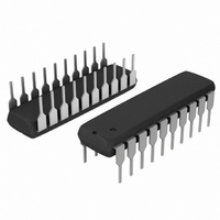
IC BUS TRANSCVR 3ST 8BIT 20DIP
Manufacturer
ON Semiconductor
Series
74HCr
Specifications of MC74HC245ANG
Logic Type
Transceiver, Non-Inverting
Number Of Elements
1
Number Of Bits Per Element
8
Current - Output High, Low
7.8mA, 7.8mA
Voltage - Supply
2 V ~ 6 V
Operating Temperature
-55°C ~ 125°C
Mounting Type
Through Hole
Package / Case
20-DIP (0.300", 7.62mm)
Logic Family
HC
Operating Supply Voltage (typ)
2.5/3.3/5V
Propagation Delay Time
165ns
Number Of Elements
1
Number Of Channels
8
Input Logic Level
CMOS
Output Logic Level
CMOS
Output Type
3-State
Package Type
PDIP
Polarity
Non-Inverting
Logical Function
Bus Transceiver
Operating Supply Voltage (min)
2V
Technology
CMOS
Operating Temp Range
-55C to 125C
Operating Temperature Classification
Military
Mounting
Through Hole
Pin Count
20
Number Of Channels Per Chip
8
Input Level
CMOS
Output Level
CMOS
High Level Output Current
- 7.8 mA
Low Level Output Current
7.8 mA
Supply Voltage (max)
6 V
Supply Voltage (min)
2 V
Maximum Operating Temperature
+ 125 C
Function
Bus Transceiver
Input Bias Current (max)
4 uA
Maximum Power Dissipation
750 mW
Minimum Operating Temperature
- 55 C
Mounting Style
Through Hole
Number Of Circuits
8
Circuit Type
Low-Power Schottky
Current, Supply
160 μA
Function Type
1-Channel
Logic Function
Transceiver
Special Features
Non-Inverting, Tri-State
Temperature, Operating, Range
-55 to +125 °C
Voltage, Supply
2 to 6 V
Logic Device Type
Transceiver, Non Inverting
Supply Voltage Range
2V To 6V
Logic Case Style
DIP
No. Of Pins
20
Operating Temperature Range
-55°C To +125°C
Filter Terminals
DIP
Rohs Compliant
Yes
Family Type
HC
Lead Free Status / RoHS Status
Lead free / RoHS Compliant
Other names
MC74HC245ANGOS


OUTPUT
A OR B
B OR A
INPUT
*Includes all probe and jig capacitance
t
Figure 3. Switching Waveform
PLH
t
r
DEVICE
UNDER
TEST
t
TLH
Figure 5. Test Circuit
10%
10%
50%
90%
50%
90%
OUTPUT
TEST POINT
C
L
t
f
*
t
PHL
t
THL
V
GND
http://onsemi.com
CC
MC74HC245A
DIRECTION
5
DEVICE
UNDER
OUTPUT
ENABLE
TEST
A OR B
A OR B
*Includes all probe and jig capacitance
OUTPUT
50%
Figure 4. Switching Waveform
TEST POINT
50%
50%
Figure 6. Test Circuit
t
t
PZL
PZH
C
1 kW
L
*
t
t
PHZ
PLZ
CONNECT TO V
TESTING t
CONNECT TO GND WHEN
TESTING t
50%
10%
90%
PLZ
PHZ
V
GND
V
GND
HIGH
IMPEDANCE
V
V
HIGH
IMPEDANCE
AND t
AND t
CC
CC
OL
OH
CC
WHEN
PZL
PZH
.
.
Related parts for MC74HC245ANG
Image
Part Number
Description
Manufacturer
Datasheet
Request
R

Part Number:
Description:
ON Semiconductor [VOLTAGE REGULATOR]
Manufacturer:
ON Semiconductor
Datasheet:
Part Number:
Description:
357-036-542-201 CARDEDGE 36POS DL .156 BLK LOPRO
Manufacturer:
ON Semiconductor
Datasheet:
Part Number:
Description:
357-036-542-201 CARDEDGE 36POS DL .156 BLK LOPRO
Manufacturer:
ON Semiconductor
Datasheet:
Part Number:
Description:
357-036-542-201 CARDEDGE 36POS DL .156 BLK LOPRO
Manufacturer:
ON Semiconductor
Datasheet:
Part Number:
Description:
357-036-542-201 CARDEDGE 36POS DL .156 BLK LOPRO
Manufacturer:
ON Semiconductor
Datasheet:
Part Number:
Description:
357-036-542-201 CARDEDGE 36POS DL .156 BLK LOPRO
Manufacturer:
ON Semiconductor
Datasheet:
Part Number:
Description:
357-036-542-201 CARDEDGE 36POS DL .156 BLK LOPRO
Manufacturer:
ON Semiconductor
Datasheet:
Part Number:
Description:
357-036-542-201 CARDEDGE 36POS DL .156 BLK LOPRO
Manufacturer:
ON Semiconductor
Datasheet:
Part Number:
Description:
357-036-542-201 CARDEDGE 36POS DL .156 BLK LOPRO
Manufacturer:
ON Semiconductor
Datasheet:
Part Number:
Description:
357-036-542-201 CARDEDGE 36POS DL .156 BLK LOPRO
Manufacturer:
ON Semiconductor
Datasheet:
Part Number:
Description:
357-036-542-201 CARDEDGE 36POS DL .156 BLK LOPRO
Manufacturer:
ON Semiconductor
Datasheet:
Part Number:
Description:
Manufacturer:
ON Semiconductor
Datasheet:
Part Number:
Description:
Manufacturer:
ON Semiconductor
Datasheet:
Part Number:
Description:
Manufacturer:
ON Semiconductor
Datasheet: